VOGONS


Reply 20 of 48, by kolderman

User metadata
Rank l33t
Rank
l33t
H3nrik V! wrote on 2020-09-12, 08:13:
kolderman wrote on 2020-09-12, 08:11:

I thought the ppro had a kind of oblong die shape. Nice photo tho.

The package has, as there is actually two dies in it - the CPU and the cache ..

And is the photo of the cpu? Looks more like a memory ic to me.

Reply 21 of 48, by imi

User metadata
Rank l33t
Rank
l33t

that's what I thought at first too, because it looked so uniform, but if you check other pictures you'll see that that is indeed the CPU die and the cache looks quite different ^^

cache is on the left: http://www.cpushack.com/wp-content/uploads/20 … 013_die_big.jpg

Reply 22 of 48, by digger

User metadata
Rank Oldbie
Rank
Oldbie

Wow, those pictures are gorgeous. At first glance, I wouldn't even have guessed that those were actual pictures. They look close enough to perfect to be taken for 3D renderings.

Reply 26 of 48, by donkom

User metadata
Rank Newbie
Rank
Newbie

Ah, here she is - the Pentium 60. 800nm manufacturing process, this chip is huge. S-Spec SX835so this is a C1 stepping with the FDIV bug.

Pentium60-A80501-60-SX835.jpg

Really a wonderful chip to photograph, and aside from a few bent pins it would probably, at least in the short term, still be a functional CPU if I put it in a compatible system (which sadly, I don't have). STill, I have some questions about this particular chip!

On a number of Intel processors there appears to be numbers in the corner of the cavity:

P60-C1-closeup1.jpg

In this case, "4094". It's a code for something, but what? I might imagine that the "C" refers to the stepping. When you get into the actual silicon there are some weirdness too:

P60-C1-closeup2.jpg

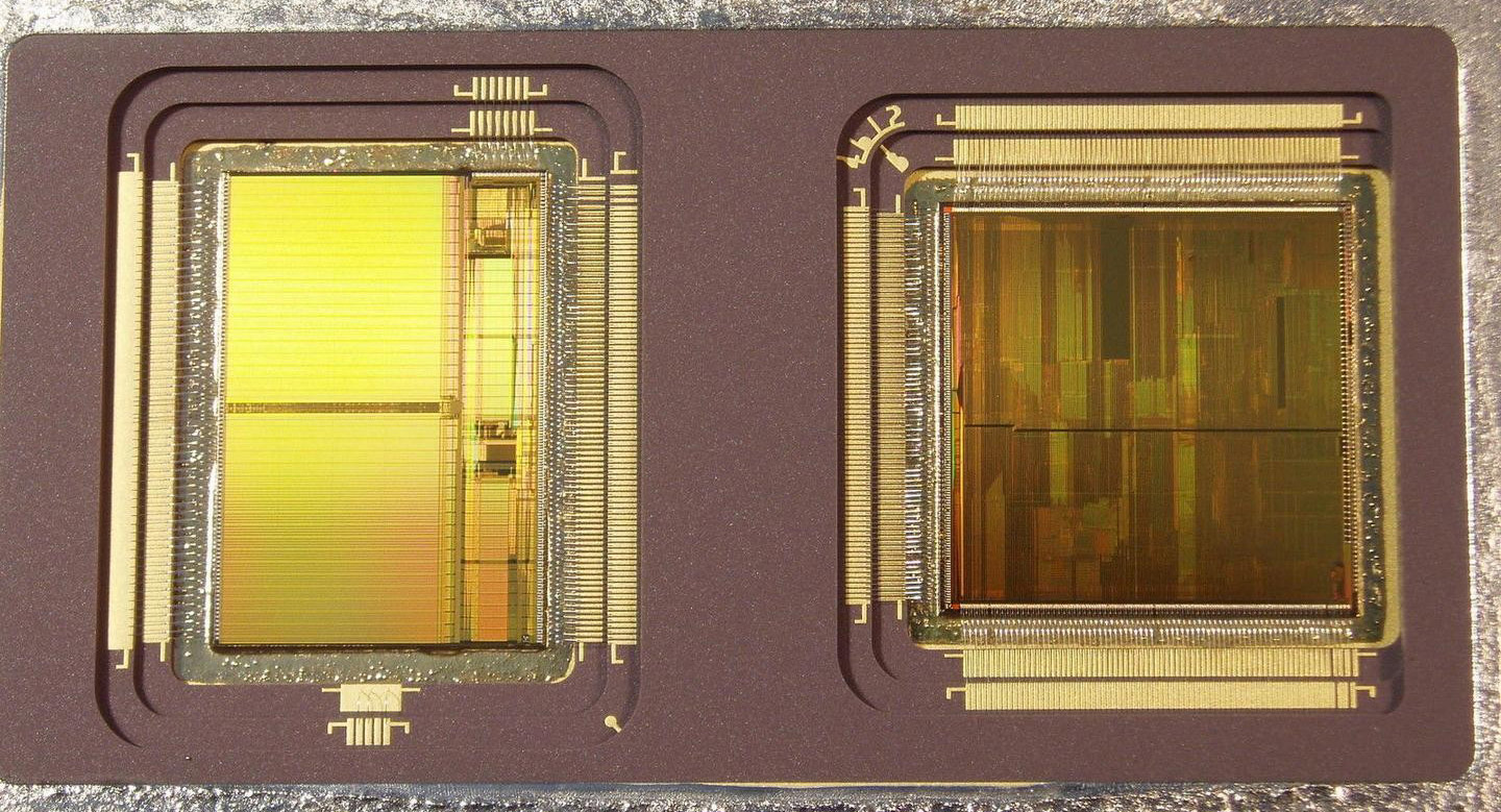
What's that diagonal line doing - some sort of shortcut? There's also this quizzical rectangle of two triangles - is that just filling in random space? Hunting around, we find even more worth questioning:

P60-C1-closeup3.jpg

It looks like there's something on top of the die - an extra layer partially covering the diagonal red lines, but they are still visible below this odd covering. I wonder what the purpose is. And then you can't help but notice that super ominous triangle! What is it's purpose? Is it like a hidden Easter egg? Is it the way out of the maze if an electron was a maze runner?

Anyhow, this was a fun chip to photograph. Used three point light sources (flashlights) at different angles to get the full chip to be illuminated as you see it, while simultaneously firing a ring flash from the side to illuminate the chip cavity. The area beyond the cavity is artificially generated using the same texture as the ceramic to remove the solder and pins that would otherwise be on the chip.

Reply 27 of 48, by donkom

User metadata
Rank Newbie
Rank
Newbie

Also, people have been asking how these images are taken. Like so:

_1091347.jpg

Three flashlight used at very specific angles - which are affected by the position of the chip, the angle the chip is placed, the angle of the camera to the chip, and the position and angle of the lights. A lot of guesswork to get it right. Here's another view:

_1091352.jpg

The camera is a Lumix S1R and the lens is a Canon MP-E 65mm F/2.8 1x-5x macro lens. In this setup the die is so massive I only use the lens at 1x magnification, but for smaller dies I can fill the frame easily with the same setup.

_1091355.jpg

The screen can be angled to that when adjusting the lights I have the ability to see the immediate effect on the image. The camera is also on an automated focusing rail, a Novoflex CASTEL-MICRO, which allows for very accurate adjustments to move the camera forward and back, taking images at different focus points which are then combined together. This focus stacking technique wouldn't be required if the silicon was parallel to the focal plane of the camera - a "straight on" shot. It is required when shooting at these more extreme angles however. I make it much more difficult for myself shooting them this way, but I enjoy the final images much more.

Reply 28 of 48, by imi

User metadata
Rank l33t
Rank
l33t

ooooh S1R, some serious gear there very nice ^^

doesn't moving the camera for focusing also change the framing a tiny little bit when stacking? or is that negligible?

would it be possible to do accurate focus stacking with some remote control software setting the focus in increments?

Reply 29 of 48, by donkom

User metadata
Rank Newbie
Rank
Newbie
imi wrote on 2020-09-13, 16:33:

ooooh S1R, some serious gear there very nice ^^

doesn't moving the camera for focusing also change the framing a tiny little bit when stacking? or is that negligible?

would it be possible to do accurate focus stacking with some remote control software setting the focus in increments?

Moving the camera is the preferred way to do focus stacking. Even though the lens is not telecentric, the amount of adjustments are minimal. I also have some nearly-telecentric microscope objectives from 2x to 100x that I use in certain cases. By shifting the focal plane of the camera and only caring about the details that are in focus in any given shot, you remove most of the problems and the rest is handled computationally.

While some cameras do offer focus stacking the camera body itself (or simply focus bracketing), this is a bigger issue. When you change the focus of a lens, you also slightly change the focal length, and thereby change the field of view (this is commonly referred to as "focus breathing"). When you align these images to stack, they'll nest inside of each-other link Russian stacking dolls and you have to throw away everything outside of the "smallest" inner frame... not to mention potential alignment issues with the shifting perspective.

I have contemplated shooting one of these images using the high-res mode of the Lumix S1R which generates 187MP files. if I swap out the flash for a diffused flashlight I could do this - but dealing with the focus stack would be... problematic. Maybe if I get a super special chip I'll consider that - there always more detail to uncover. 😀

Reply 32 of 48, by H3nrik V!

User metadata
Rank Oldbie
Rank
Oldbie
appiah4 wrote on 2020-09-14, 06:56:

4094 is probably date code - 40th week of 1994.

Sounds plausible.

If OP could post a picture of the top of the CPU, it would be easy to confirm 😀

Please use the "quote" option if asking questions to what I write - it will really up the chances of me noticing 😀

Reply 33 of 48, by appiah4

User metadata
Rank l33t++
Rank
l33t++
H3nrik V! wrote on 2020-09-14, 17:26:
appiah4 wrote on 2020-09-14, 06:56:

4094 is probably date code - 40th week of 1994.

Sounds plausible.

If OP could post a picture of the top of the CPU, it would be easy to confirm 😀

Not necesserily, the production of the die and the production of the CPU could be months or even years apart.

Retronautics: A digital gallery of my retro computers, hardware and projects.

Reply 34 of 48, by donkom

User metadata
Rank Newbie
Rank
Newbie

A80501-60 SX835
ICOMP INDEX=510
L4352836-0750
INTEL (M)(C)1992

54160120AB
MALAY 437 F

Wish I I knew how to read Intel date codes. From the copyright it seems like a 1992 chip, otherwise they would have updated that in subsequent years I think. Note that the numbers 4094 are inside the ceramic package but not on the silicon itself.

Reply 35 of 48, by cyclone3d

User metadata
Rank l33t++
Rank
l33t++

35th week of 94

L4352836-0750

HOWTO: Read an Intel CPU FPO/Batch Code Example: L707A723 --- […]
Show full quote

HOWTO: Read an Intel CPU FPO/Batch Code
Example: L707A723 ---

1st letter or digit = plant code: (Malaysia)
0 = San Jose, Costa Rica
1 = Cavite, Philippines
3 = Costa Rica
6 = Chandler, Arizona
7 = Philippines
8 = Leixlip, Ireland
9 = Penang, Malaysia
L = Malaysia
Q = Malaysia
R = Manila, Philippines
Y = Leixlip, Ireland

2nd digit = Year of production: (2007)
3rd & 4th digits = week: (7th week )
5th - 8th digits= lot number: (723)
10th - 13th digits = serialization code (---)

https://rog.asus.com/forum/showthread.php?278 … -FPO-Batch-Code

Another link:
https://cpumuseum.jimdofree.com/guides-tutori … identification/

Last edited by cyclone3d on 2020-09-14, 19:01. Edited 1 time in total.

Yamaha modified setupds and drivers
Yamaha XG repository
YMF7x4 Guide
Aopen AW744L II SB-LINK