VOGONS


Yet another 286 build.

Topic actions

Reply 140 of 171, by MarkP

User metadata
Rank Member
Rank
Member
simon_e_hall wrote on 2022-07-15, 13:36:

Never had any issues as I usually use bundled/ rounded cables in my builds, probably because my chain of SCSI devices are usually limited in number and over a very short distance, so signal loss/ interference is not to bad. Think my cable thing is a hang up from the 90's (maybe early 2000's), when they were suppose to improve cooling and came in all sorts of colours and I thought looked cool and tidy.

However, what I do have in my cable collection is this DELL (or even Compaq) OEM twisted pair bundled cable, so I have installed that, it is a bit longer than the previous one but has an edge connector.

Bundling like that has been done for decades in the aviation industry.

Before plastic tyraps we used waxed cotton tape-miles of the stuff;) Once the service panels were put on you couldn't see it any way.

Reply 141 of 171, by Jo22

User metadata
Rank l33t++
Rank
l33t++

Colored ribbon cables are (almost) an industry standard, I think.
They're really cool and around since the 1970s or so.
The purpose of the colours is to assist wiring of the individual wires.
If they all were mono colour, electricians/technicians/.. had much more trouble
counting wires and would thus mess up things more quickly.
The colours are following a reoccuring pattern, also, if memory serves.
That's why they look rainbow style. 🌈

Seller (just an example) :

https://www.reichelt.com/de/en/flat-ribbon-ca … -3m-p47677.html

"Time, it seems, doesn't flow. For some it's fast, for some it's slow.
In what to one race is no time at all, another race can rise and fall..." - The Minstrel

//My video channel//

Reply 142 of 171, by MarkP

User metadata
Rank Member
Rank
Member
Jo22 wrote on 2022-07-20, 21:48:
Colored ribbon cables are (almost) an industry standard, I think. They're really cool and around since the 1970s or so. The purp […]
Show full quote

Colored ribbon cables are (almost) an industry standard, I think.
They're really cool and around since the 1970s or so.
The purpose of the colours is to assist wiring of the individual wires.
If they all were mono colour, electricians/technicians/.. had much more trouble
counting wires and would thus mess up things more quickly.
The colours are following a reoccuring pattern, also, if memory serves.
That's why they look rainbow style. 🌈

Seller (just an example) :

https://www.reichelt.com/de/en/flat-ribbon-ca … -3m-p47677.html

I've never seen it used in an aircraft all going from cockpit to tail section. In something fridge sized or some other enclosed units/electronic equipment yes. I've seen it in old CRT TVs and such.

It's generally sold in smallish lengths unless you are a electronic repair/service/manufacturing business.

Reply 143 of 171, by pentiumspeed

User metadata
Rank l33t
Rank
l33t

In aircraft and miltary aircrafts, The wiring is white due to plastic they required has higher fire resistance.

Cheers,

Great Northern aka Canada.

Reply 144 of 171, by MarkP

User metadata
Rank Member
Rank
Member
pentiumspeed wrote on 2022-07-20, 22:42:

In aircraft and miltary aircrafts, The wiring is white due to plastic they required has higher fire resistance.

Cheers,

They're heavily shielded and text is easy to read as well as being easier to route.

Reply 145 of 171, by Jo22

User metadata
Rank l33t++
Rank
l33t++

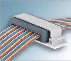
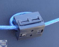
Generally speaking, ideally, if someone wants to reduce the noise level, a ferrite core can be attached to a cable (at both ends).
It will reduce sheet waves assumed traviling at the outside of the mantle, reduce common mode currents, effectively also reducing effects of cross-talk, too.

Cables (incl. ribbon cables) can either be carefully wound through such ferrites or the ferrites can be added like a clip.
Flat ferrite chokes also exist nowadays, it seems.
Of course, using cables with extra grounding lines in between can reduce noise levels, too.
That's the alternative, the cheaper and more economical solution.
It's as if we're using twisted-pair (RJ45, RJ11) vs properly shielded coaxial cables or optical connections. 😂

https://electronics.stackexchange.com/questio … k-to-reduce-emc

https://en.wikipedia.org/wiki/Network_isolator

Attachments

  • wEXNP.jpg
    Filename
    wEXNP.jpg
    File size
    4.86 KiB
    Views
    996 views
    File license
    Fair use/fair dealing exception
  • SX4Ic.jpg
    Filename
    SX4Ic.jpg
    File size
    7.06 KiB
    Views
    996 views
    File license
    Fair use/fair dealing exception
  • images(3).jpg
    Filename
    images(3).jpg
    File size
    7.69 KiB
    Views
    996 views
    File license
    Fair use/fair dealing exception

"Time, it seems, doesn't flow. For some it's fast, for some it's slow.
In what to one race is no time at all, another race can rise and fall..." - The Minstrel

//My video channel//

Reply 147 of 171, by Jo22

User metadata
Rank l33t++
Rank
l33t++
MarkP wrote on 2022-07-21, 05:25:

Looks like we a drifting off the topic.

Now what was it again? Ah yeah, 286s 😉

Nah, just a tiny bit. 😁 Those ferrites have a place in vintage PCs, too.
Adding them to all peripherals makes sense, enhances stability. Mice, keyboards, speakers, VGA cables, power cords etc.

RFI is an issue that's especially of interest for systems running at shortwave frequencies (below 30MHz, maybe 50MHz).

That's what's so ironic, I think.
An old, "harmless" XT/AT causes more noise on the HF bands than a 586 class PC.

Because its fundamental wave is in HF spectrum, not just an harmonic.

Sure, a Pentium PC may also cause issues at VHF/UHF bands (~90 MHz and up),
but there, the more robust FM is often used.
Well, air band excluded, which uses AM.
The third harmonic is the most annoying one, perhaps, btw.

Edit: No worries, I'm finished with the RFI topic. 🙂👍

"Time, it seems, doesn't flow. For some it's fast, for some it's slow.
In what to one race is no time at all, another race can rise and fall..." - The Minstrel

//My video channel//

Reply 148 of 171, by simon_e_hall

User metadata
Rank Member
Rank
Member
pshipkov wrote on 2022-07-20, 18:56:

Too bad stability issues are striking again.
We went over it once or twice already in previous posts, but again - i am confident that the jumper settings you used as a reference from the picture i provided are correct and work really well with all settings on max, maxed-out RAM, 0-waits and 25-30MHz frequency range.
Good chance you have flaky RAM modules.

There might be some slight differences between our boards then especially with the top row of jumpers, I have mapped the pins listed below a few other things I have discovered:

The issue with 4mb RAM modules not being detected properly is solved and so, so simple, just a simple BIOS setting, the 384 relocate option which I have mentioned before.

When I booted during testing with 16mb (or 8mb when fault finding if a module was a problem) with jumpers as per @pshipkov computer it would only report 640kb, which confused me as the machine was obviously seeing some RAM to allow boot and see 640kb, also it would boot into DOS, thinking it was not seeing the whole module. Of note, during testing I did not have a battery connected.

The option to allocate 384kb and make it extended memory is enabled by default when the BIOS starts with its default settings (i.e. when started with no battery), when I disabled this option it today (don't know why I thought of it), the boot showed 7808kb, so therefore only half the SIMM banks where detected, don't know how I missed this.

Previously I suspect that a jumper or jumpers would have something to do with the selection of DRAM or SIMM but previously had no luck working it out (probably because of that damn BIOS option reporting the wrong detected RAM).

The jumpers work in groups of three, the pattern easily seen when I traced them previously. So shorting all jumpers between pins 2 and 3 the system would not boot, now as I have nothing in the DRAM sockets would suggest pin 3 connects the DRAM sockects. Shorting all jumpers between pins 1 and 2 allows boot with all 16mb found, suggesting pin 1 connects the SIMM sockets, would of figured this out far earlier if the RAM size reported as they should of.

As per the reference board:
shorting pins 2 and 3 on JP 3 to 5
shorting pins 1 and 2 on JP 6 to 8, only activates two of the SIMM sockets.

So I tried it the other way around:
shorting pins 1 and 2 on JP 3 to 5
shorting pins 2 and 3 on JP 6 to 8, causings no POST (might have done with DRAM installed).

The pins mapped would also reflect this

JP8 Pin 1 RAS0*
JP8 Pin 3 RAS2*

JP7 Pin 1 CASL0*
JP7 Pin 3 CASL2*

JP6 Pin 1 CASH0*
JP6 Pin 3 CASH2*

JP5 Pin 1 RAS1*
JP5 Pin 3 RAS3*

JP4 Pin 1 CASL1*
JP4 Pin 3 CASL3*

JP3 Pin 1 CASH1*
JP3 PIn 3 CASH3*

Sorry for the long winded post.

But the question remains why is the shadow option causing random freezes? Ran a burn-in test over night and no crashes what so ever, RAM tests also suggest the modules are all good.
Last edited by simon_e_hall on 2022-07-23, 15:02. Edited 2 times in total.

Reply 150 of 171, by simon_e_hall

User metadata
Rank Member
Rank
Member
maxtherabbit wrote on 2022-07-23, 13:03:

Remind me which video card you're trying to shadow again

Diamond Flower WG-5000, not familar with the make but based on the ET4000/W32 with 1mb of RAM.

https://stason.org/TULARC/pc/graphics-cards/C … GA-WG-5000.html

Reply 152 of 171, by simon_e_hall

User metadata
Rank Member
Rank
Member
maxtherabbit wrote on 2022-07-23, 15:47:

Does your system offer separate settings to shadow the system and video BIOSes, or is it all or nothing?

Do you mean the ability to shadow one or the other or both? To do basic fault finding to identify the issue? If so trying it at the moment with a burn-in test again, enabling each one seperatly until the fault appears.

Reply 153 of 171, by simon_e_hall

User metadata
Rank Member
Rank
Member

Well it appears shadowing the System ROM causings some IDE operations to crash, fired up AMI Setup to see the hidden options in the BIOS to see if anything in there would help, but no joy.

Of note, shadowing the video BIOS has no affect, does not even seem to increase performance on benchmarks.

Reply 154 of 171, by simon_e_hall

User metadata
Rank Member
Rank
Member

This weekend is chasing those realiability issues, been running multiple tests, removing cards, swapping module and cards, etc and well:

1) RAM: Extensive testing of the 4Mb RAM modules, these pass all tests and have worked perfectly in the past with no issues, I activated the hidden option in the BIOS for parity checks, which the chipset should support, but doing certain tasks creates a pairty error and causes the system to stop, e.g. MSD memory check/ diagnostic. However, these pass all memory tests I can find and run in this motherboard.

Now I know these modules work perfectly with parity checking on in another memory board. So maybe there is something about these modules the chipset does not like. So have downgraded back to the 1mb modules and system seems to like that, not too concerned about the downgrade, as 16Mb is overkill.

2) SCSI: I did the SCSI card self diagnostics and after several loops ( up to 40 usually) of the test the system would freeze, so removed that and gone back to IDE which again is not really an issue and now gives me a free ISA slot. Again, burn in testing has not failed yet since removing that. The documentation states to lower the speed of the card if this happens, but it occurs on the lowest setting, tried different DMA/ IRQs as well to assure it was not hardware issues, even though the resources I assigned when I set it up should not conflict, just wanted to check everything.

Again I know this SCSI card is fine and works perfectly in another motherboard and will loop constantly. So a bit of a downgrade but using Compact Flash anyway so not really an issue.

3) The datasheet for the PT-606E I was using, I have discovered is not 100% correct for the jumper settings for disabling COM2's/ IRQ, so would cause a conflict with the installed MODEM which is set to COM2. Not really a problem a bit of trouble shooting to identify the correct jumper.

4) Finally, my mistake this time for the PT-606E, by putting a jumper in the wrong place causing a DMA issue now and then, easily corrected by putting it in the right place!

So not sure what is going on with the first two issues, maybe this board and chipset is rather picky as I know the RAM/ SCSI work fine in other systems. Although downgrades it will not really affect what I can do with the system. Approaching the 200 loop of the PC Diagnostics '95 burn in test at the moment.

So hopefully all good now.

Reply 155 of 171, by maxtherabbit

User metadata
Rank l33t
Rank
l33t

I'm starting to think your chipset is just marginal. I know it's not what you'd want to hear but it seems the results are stacking up in that camp. Both known good cards and memory only not working in one specific board...

Reply 156 of 171, by pshipkov

User metadata
Rank Oldbie
Rank
Oldbie

While i didnt try scsi on the same mobo here, i pushed it hard and it handles 31 mhz, which is simply not trivial.
Took with ease any decent 1 and 4 mb memory modules, several different graphics adapters, a standard ide controller with cf storage device, worked fine with sb pro 2 and ess1689.
It is unfortunate that Simon has issues, especially with ram.

retro bits and bytes

Reply 157 of 171, by simon_e_hall

User metadata
Rank Member
Rank
Member
pshipkov wrote on 2022-07-30, 22:52:

While i didnt try scsi on the same mobo here, i pushed it hard and it handles 31 mhz, which is simply not trivial.
Took with ease any decent 1 and 4 mb memory modules, several different graphics adapters, a standard ide controller with cf storage device, worked fine with sb pro 2 and ess1689.
It is unfortunate that Simon has issues, especially with ram.

Mine would not post with the SB Pro 2 in which is just odd, but since those changes everything has been stable all weekend, mostly playing Wolf 3D and tinkering with Win 3.1 games.

I have a feeling my board will flat out not work if I try to push it hard, in fact might try it quickly today.

Edit: Tried 30Mhz POST passed with no issues. However, when it tried to boot from the hard drive it failed, did not even get the 'Starting MS-DOS...' message, just a flashing cursor under the summary screen, so went better than expected! Not really too concerned about overclock at the moment, might have a dig around and see what other crystals I have here and try a lower overclock at somepoint.

Also distracted playing Lemmings

Reply 158 of 171, by simon_e_hall

User metadata
Rank Member
Rank
Member

Things have a slight change in the build this week and a bit of testing.

First wanted to find a controller card in my collection that would boot if I was running at 30Mhz, I did not find any (then again the motherboard maybe the issue), shame. But I ended up clearing up my project room and organising things where I found a Promise DC-200 IDE cache controller. So thought I would try that along with a SIIG LPT/ COM card to see if that would work at 30Mhz, again no. But it is rather cool having an IDE cache controller in there.

It is also a bit funny as the controller has an onboard 80286-20 CPU, tested that and it works nicely can even shadow the BIOS of the card with no crashes.

Also whilst I was reading the chipset datasheet I came accross an intresting part that said anything over 16mb is mapped as EMS RAM on the chipset, so a while ago I had it running with both 16mb SIMM and 1mb socketed RAM and it was thought these RAM modules where probably overlapping. So I tested it out, installed the driver with the socketed RAM missing and no EMS was allocated/ in fact the system would freeze.

So for a bit of fault finding installed the DC-200 BIOS into the location of where the page frame would go and sure enough the driver came back saying no space for the page frame, so driver works and is scanning the upper memory, etc.

Installed the 1mb of socketed RAM and the EMS driver kicked in, it does not use the whole 1mb, saying about 740Kb free and 320Kb actually usable, so probably a few device switches need a tweak.
Of course the RAM jumpers all needed shorting between pins 2 and 3, which is a little confusing but it works.

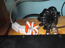
Also found some ferrite cores for the bundled cables for a rather intresting look.

Reply 159 of 171, by pshipkov

User metadata
Rank Oldbie
Rank
Oldbie

Pretty sure the 30mhz issue is RAM related.
99 out of 100 cases is the memory chips not able to cope with the frequency.

So, with the DC-200 IDE you can claim "dual" 286 PC ; )

retro bits and bytes