DerBaum wrote on 2022-08-04, 16:13:Its not always a ground trace. Sometimes it is something different. But in your case the one we are talking about is ground. […]
Show full quote
Rocket202 wrote on 2022-08-04, 15:33:Okey now is really done. […]
Show full quote
Okey now is really done.
My multimeter has only one mode "diodes and test continuity", it has something like "test isgnal" (putting 5v if understood correctly, but i dont think is this one).
About this test it said: if the resistance is less than 50ohm is going to beep.
Al has done the beep in the - side of the capacitors with a resistance of 0.002, and in the other side (+) 365ma for all of them instead on the ones i didnt already replace, it says something like 800-900 etc (depends)
What i dont understand, if you said that "giant gold trace" is the ground, sometimes is in the + side, other times in - side.
Its not always a ground trace. Sometimes it is something different. But in your case the one we are talking about is ground.
Of course you will measure something different if you measure other pins then ground. Dont try everything at once. Stay with the things we said.
0.002 is fine from ground to ground. it is good enough for this measurement.
Yes diode mode is often the same position as beep mode. Thats ok.
Thank you for clarify this andr you patience, really helpful 😀 , im going test the pc right now but i think it will run for sure, if you think that i have to check something just say.
majestyk wrote on 2022-08-04, 16:14:
Rocket202 wrote on 2022-08-04, 13:21:
In case that is ground they can be grounded by another point of the motherboard?, or it has to be obligatorily connected to that track next to the condenser? (repair the track)
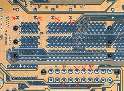
Ground connections need to be as short as possible so just remove a bit of the coating next to the capacitor pin and solder the copper directly with the capacitor´s negative pin.
By the way I`m not that pessimistic here. There are 4 small traces from ground to each pin and it´s very unlikely you destroyed all 4 of them.
What a surprise that no one said that, just ironic.
Being honest, i worked in contruction building very heavy and light metal structures, i have done an electrode welder course and if i explane you how to operate to me is pretty simple, ill tell you how you have to use the machine (intensity depends the electrode etc) and >how the material works<, if you through too much intensity to a very thin metal youll makes holes or whatever, is pretty basic, agree right?
So i was thinking now about this, how is possible that i search a lot of info, tips, newbie fails etc and now one, literally no one spoke about the ground traces, they are pretty easy to blow. do not want to teach in detail?.(perhaps worried that they will lose their jobs)
So anyway, thanks for everyone helped me, it has helped me a lot, most of the people here have helped me a lot, is a good place.
rasz_pl wrote on 2022-08-04, 16:17:
Rocket202 wrote on 2022-08-04, 13:58:
you have answered my question, if it dosnt have ground i can solder a wire to any other grounded point
no, because impedance of such connection will be huge. What you can do is scrape remaining ground connected copper near destroyed pads and flow more solder over it.
🍿
Ah okey, i see, so if i scratch very carefully those "ground traces" i can find the copper?, I thought about it, it is very thin didn't try in case i destroy it.
"all that golden ground" is one layer right?, i mean, is just an unique point of conection not a lot inside of it right?
Without it still having ground, probably there is a reason to have more than 1 like Majestik said, but is working, if i can repare it ill do it, but it still having ground, otherwise when i connect the computer it would not have started surely