Reply 20 of 217, by rasteri
Rank
Member
sofakng wrote on 2022-11-19, 02:40:Just ordered some PCBs ... Looking forward to giving this a try!
Which version you get? The PS/2 or the new serial one?
sofakng wrote on 2022-11-19, 02:40:Just ordered some PCBs ... Looking forward to giving this a try!
Which version you get? The PS/2 or the new serial one?
rasteri wrote on 2022-11-19, 03:28:sofakng wrote on 2022-11-19, 02:40:Just ordered some PCBs ... Looking forward to giving this a try!
Which version you get? The PS/2 or the new serial one?
Is it even released? 😉 share haha
naa, nothing yet...
tabm0de wrote on 2022-11-19, 07:28:Is it even released? 😉 share haha
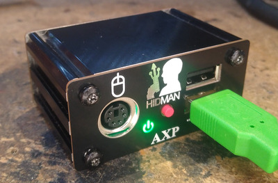
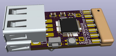
Yeah the version in github is the serial version (I call it the AXP). I ask because it's not fully tested yet...
Still a lot of stuff to do but nearly there.

Ahhh -- oops! It looks like I ordered the serial version. I wasn't aware of the difference and just noticed your project as I was placing an order for other PCBs.
What's the difference between the two projects?
EDIT: Actually I'm not sure what I ordered? I used the gerbers.zip from your github (https://github.com/rasteri/HIDman/blob/main/h … ers/gerbers.zip)
sofakng wrote on 2022-11-22, 21:15:Ahhh -- oops! It looks like I ordered the serial version. I wasn't aware of the difference and just noticed your project as I was placing an order for other PCBs.
What's the difference between the two projects?
EDIT: Actually I'm not sure what I ordered? I used the gerbers.zip from your github (https://github.com/rasteri/HIDman/blob/main/h … ers/gerbers.zip)
Yeah that's the serial version. I'm still debugging it but it should work - keep an eye on this thread for updates.
Just a curious question, will the serial model be tested on dos/windows x.x to windows 98? It’s feels the safes device to get then instead of the ps/2 for me as later version can handle usb anyway, that is if the ps/2 would not work with a serial adapter :p
naa, nothing yet...
tabm0de wrote on 2022-11-23, 16:25:Just a curious question, will the serial model be tested on dos/windows x.x to windows 98?
That's the plan.
@rasteri - Very cool project!
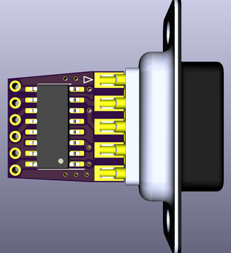
I have some spare space on my next PCB panel that's about to go out, so I thought I'd jump in and make a few of these.
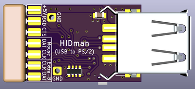
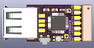
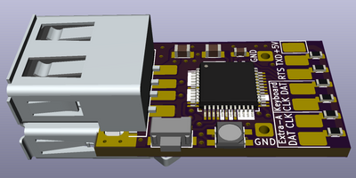
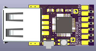
I wanted something much smaller, with integrated cables... closer to the PS/2 to USB dongles one can get (that work in reverse). So, here's what I came up with based on the current schematic in your GitHub repo. (Note: Some of the 3D models aren't 100% accurate, so the finished product will be slightly more refined)
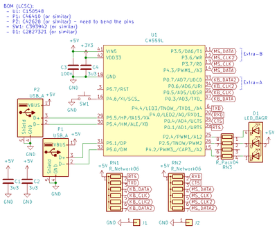
The PS/2 KB/Mouse cables would be directly soldered to the pads that the (6x) resistor networks on the right side of the board are soldered to. I also broke out the Serial lines should I ever decide to emulate a Serial mouse. The MAX232 and required resistors would be on a small PCB located inside the DB9 connector (should be just enough room).
I am using two separate USB connectors instead of a combo connector. For most of my systems, I'll only use this with a Logitech Wireless Combo KB/Mouse USB adapter, so I'll only need to install the lower USB port (P1), which can be installed roughly in-line with the middle of the PCB edge. This will keep a really slim profile for the whole adapter. I did leave support for the secondary USB port on the top as well in case I ever need separate USB KB/Mouse inputs.
Do you mind giving this a quick look over to see if anything jumps out as problematic? Have you run across any changes you were thinking of for the next version that I should try and incorporate?
Following this in the hope that there will be an AT Keyboard / Serial version of this some time so I can build it.
Retronautics: A digital gallery of my retro computers, hardware and projects.
serisman wrote on 2022-11-24, 06:11:Do you mind giving this a quick look over to see if anything jumps out as problematic? Have you run across any changes you were thinking of for the next version that I should try and incorporate?
Looks really great! I was thinking of doing something similar originally but I wanted the PCBs to be manufacturable without manually soldering on wires so I decided on the DIN ports instead.
I haven't tested this pinout fully yet - if you can wait a couple of days I should have it tested by the end of the weekend.
EDIT : what are you planning to do for an enclosure? 3D printed?
appiah4 wrote on 2022-11-24, 06:24:Following this in the hope that there will be an AT Keyboard / Serial version of this some time so I can build it.
The current version should support AT and serial (you'll need a passive PS/2 to AT adapter but they're super cheap) - I have to do some more coding but we're nearly there.
rasteri wrote on 2022-11-25, 12:30:Looks really great! I was thinking of doing something similar originally but I wanted the PCBs to be manufacturable without manu […]
serisman wrote on 2022-11-24, 06:11:Do you mind giving this a quick look over to see if anything jumps out as problematic? Have you run across any changes you were thinking of for the next version that I should try and incorporate?
Looks really great! I was thinking of doing something similar originally but I wanted the PCBs to be manufacturable without manually soldering on wires so I decided on the DIN ports instead.
I haven't tested this pinout fully yet - if you can wait a couple of days I should have it tested by the end of the weekend.
EDIT : what are you planning to do for an enclosure? 3D printed?
appiah4 wrote on 2022-11-24, 06:24:Following this in the hope that there will be an AT Keyboard / Serial version of this some time so I can build it.
The current version should support AT and serial (you'll need a passive PS/2 to AT adapter but they're super cheap) - I have to do some more coding but we're nearly there.
Oh cool! I have those adapters, incidentally (AT to PS/2 and Serial to PS/2). I guess I ought to build this 😁
Retronautics: A digital gallery of my retro computers, hardware and projects.
appiah4 wrote on 2022-11-25, 13:42:Oh cool! I have those adapters, incidentally (AT to PS/2 and Serial to PS/2). I guess I ought to build this 😁
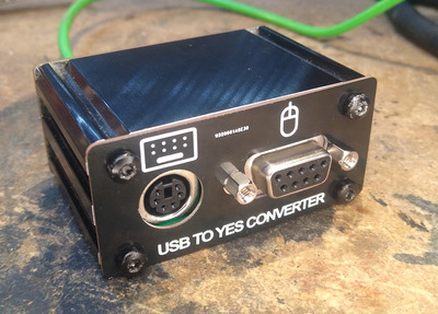
Unfortunately converting PS/2 to serial won't work (the adapter pinouts vary so much between different manufacturers that it would have been impossible to support them all safely), but the latest HIDman board has a serial port on it :
Rasteri, do you have a BOM for the projects?
Also, what's the difference between the two versions of your project? It looks like one outputs the mouse over serial and the other is over PS/2? What about the KBD?
sofakng wrote on 2022-11-25, 16:10:Rasteri, do you have a BOM for the projects?
Also, what's the difference between the two versions of your project? It looks like one outputs the mouse over serial and the other is over PS/2? What about the KBD?
No BOM until it's fully complete.
The PS/2 version has two PS/2 ports (Keyboard & mouse), the AXP verison has two PS/2 ports (keyboard/mouse) AND a serial port (just mouse). You can still use the AXP on PS/2 devices no problem.
Ahh, OK... It sounds like the AXP version will have more features (ie. added serial port).
I think that's the version I ordered PCBs for so I'll keep an eye on the project and order parts after everything is finalized (and hopefully the PCB doesn't need to change).
Thanks much!
rasteri wrote on 2022-11-25, 12:30:Looks really great! I was thinking of doing something similar originally but I wanted the PCBs to be manufacturable without manually soldering on wires so I decided on the DIN ports instead.
I haven't tested this pinout fully yet - if you can wait a couple of days I should have it tested by the end of the weekend.
EDIT : what are you planning to do for an enclosure? 3D printed?
Thanks for checking it over for me. Yeah, your version is definitely easier to manufacture and more premium looking. For my setup, though, I would rather not have such a large external box with long cables.
I went ahead and added it to my PCB order. I can always spin a new version in the future if there are important changes that need to be incorporated. It looks pretty safe to me though. The serial pins can't really change if we want to continue to use hardware serial, and the PS/2 pins look like just standard GPIOs so are probably less important where they map to.
I did make a few tweaks to my (mini) PCB. Primarily switching to SMD pull-up resistors instead of the SIP resistor networks. I realized I don't have the correct SIP RNs on hand anyway, and the individual resistors gives more flexibility in tweaking values (or leaving unconnected if needed). Speaking of which... your schematic doesn't specify values for any of the pull-ups. I assume the PS/2 ones are 4.7k to 10k and the LED ones are 330 to 1k? I added optional pull-ups for the serial lines as well, not sure if they are useful or not?
Yes, I plan on designing a 3D printed enclosure, or maybe even just use some clear heatshrink tubing.
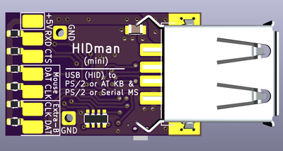
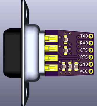
Oh, I also designed a small PCB for the serial extension that can be embedded directly inside a DB9 shell.
Both designs are available on OSHPARK, although keep in mind these are not yet fully tested designs. I'll add them to a github repo once confirmed working.
HIDman (mini): https://oshpark.com/shared_projects/GPxhWAbz
Serial DB9 to TTL: https://oshpark.com/shared_projects/djSCnWyn
serisman wrote on 2022-11-25, 19:47:Speaking of which... your schematic doesn't specify values for any of the pull-ups. I assume the PS/2 ones are 4.7k to 10k and the LED ones are 330 to 1k?
I'm using 2.2K for the PS/2 pullups, that seems to be what's inside most keyboards. My current proto uses 1K for the LEDs but I might switch to 2.2K for BOM optimization purposes (they don't need to be very bright).
I added optional pull-ups for the serial lines as well, not sure if they are useful or not?
No better not populate those, they could damage things (if you left the serial connected while the HIDman is unpowered then you could cause VCC to rise to RS232 voltages, i.e. +-15V)
rasteri wrote on 2022-11-25, 21:22:serisman wrote on 2022-11-25, 19:47:Speaking of which... your schematic doesn't specify values for any of the pull-ups. I assume the PS/2 ones are 4.7k to 10k and the LED ones are 330 to 1k?
I'm using 2.2K for the PS/2 pullups, that seems to be what's inside most keyboards. My current proto uses 1K for the LEDs but I might switch to 2.2K for BOM optimization purposes (they don't need to be very bright).
Ok, thanks for the clarification.
rasteri wrote on 2022-11-25, 21:22:serisman wrote on 2022-11-25, 19:47:I added optional pull-ups for the serial lines as well, not sure if they are useful or not?
No better not populate those, they could damage things (if you left the serial connected while the HIDman is unpowered then you could cause VCC to rise to RS232 voltages, i.e. +-15V)
Well... they are still on the TTL side of the MAX232, so they shouldn't ever see the full +- 15V RS232 voltages. My thought was to make sure the lines were pulled high (serial Idle state) even if the external Serial module wasn't connected. But, yeah, probably not needed.
serisman wrote on 2022-11-25, 22:13:Well... they are still on the TTL side of the MAX232, so they shouldn't ever see the full +- 15V RS232 voltages. My thought was to make sure the lines were pulled high (serial Idle state) even if the external Serial module wasn't connected. But, yeah, probably not needed.
oops, I see. Yeah that's fine then.