VOGONS


Reply 120 of 456, by EduBat

User metadata
Rank Newbie
Rank
Newbie
rasteri wrote on 2023-04-10, 11:39:
I tried to get it working on the latest version of Debian (32bit), but had mixed results. I was able to get the init program por […]
Show full quote

I tried to get it working on the latest version of Debian (32bit), but had mixed results. I was able to get the init program ported easily enough, but then isapnptools wouldn't detect anything.

My guess is that since isapnptools hasn't been updated since 2007 it relies on some now-deprecated gcc feature or kernel API but I didn't do any further investigating.

I suppose next thing to try is a much older version of Linux.

I don't have any non-pnp ISA soundcards (although I theoretically could flash my CS4237-based one to disable PnP).

I haven't looked at how Debian is configured but in theory you don't have to touch isapnptools.
Modern drivers are fully pnp aware so, once again, "in theory", all you need to do is

modprobe snd-sb16

for example, for a soundblaster16.

Reply 121 of 456, by Hamby

User metadata
Rank Member
Rank
Member

This is cool! I wonder if this means I could get my Awe32 working with either my Win7 pc or my Debian Linux PC?
The Linux computer has a ASUSTeK Z8NA-D6 dual Xeon motherboard. (the American megatrends bios date is 2012).

I already have an MT32 connected to the linux computer, and would love to replace my PCI soundcard with my Awe32.

I wonder... could one attach a hercules monochrome video card via the dISApointment? I know under dos one could have a CGA/EGA/VGA and a monchrome card attached at the same time.

Another application would be vintage I/O cards; serial, parallel, gameport, ide, floppy controllers.

of course, to attach more than one isa card, one should probably attach an ISA riser to the dISAppointment.

Reply 122 of 456, by EduBat

User metadata
Rank Newbie
Rank
Newbie
Hamby wrote on 2023-04-11, 22:10:
This is cool! I wonder if this means I could get my Awe32 working with either my Win7 pc or my Debian Linux PC? The Linux comput […]
Show full quote

This is cool! I wonder if this means I could get my Awe32 working with either my Win7 pc or my Debian Linux PC?
The Linux computer has a ASUSTeK Z8NA-D6 dual Xeon motherboard. (the American megatrends bios date is 2012).

I already have an MT32 connected to the linux computer, and would love to replace my PCI soundcard with my Awe32.

I wonder... could one attach a hercules monochrome video card via the dISApointment? I know under dos one could have a CGA/EGA/VGA and a monchrome card attached at the same time.

Another application would be vintage I/O cards; serial, parallel, gameport, ide, floppy controllers.

of course, to attach more than one isa card, one should probably attach an ISA riser to the dISAppointment.

According to the manual, the ASUSTeK Z8NA-D6 does not have a tpm header, making it very hard to find all the lines of the LPC bus. Do you have a boardview file by any chance?

Regarding more slots, ideally our friend @rasteri would come up with another version ( I suggest calling it "major dISAppointment") with more ISA slots. The datasheet of the LPC to ISA bridge includes a schematic with 3 slots, suggesting it should be possible.

Reply 123 of 456, by LSS10999

User metadata
Rank Oldbie
Rank
Oldbie
Hamby wrote on 2023-04-11, 22:10:
This is cool! I wonder if this means I could get my Awe32 working with either my Win7 pc or my Debian Linux PC? The Linux comput […]
Show full quote

This is cool! I wonder if this means I could get my Awe32 working with either my Win7 pc or my Debian Linux PC?
The Linux computer has a ASUSTeK Z8NA-D6 dual Xeon motherboard. (the American megatrends bios date is 2012).

I already have an MT32 connected to the linux computer, and would love to replace my PCI soundcard with my Awe32.

I wonder... could one attach a hercules monochrome video card via the dISApointment? I know under dos one could have a CGA/EGA/VGA and a monchrome card attached at the same time.

Another application would be vintage I/O cards; serial, parallel, gameport, ide, floppy controllers.

of course, to attach more than one isa card, one should probably attach an ISA riser to the dISAppointment.

Intel LPC controller's address decoders cannot accommodate all the I/O ranges needed for AWE32/64 (EMU8000) to function. You can use an AWE32/64 but you'll have to give up some features.

From what I read in the documents, AMD LPC controller's decoders are very different from Intel's and should theoretically be able to cover the use of AWE32/64... However, some real tests are needed.

Ideally... I'm thinking if dISAppointment's form factor could be further tweaked in a way that could be easily installed inside a standard ATX case when paired with a mATX or ITX motherboard, matching the lower mounting holes of ATX boards and the ISA slot aligned to one of the case's expansion slots.

Reply 125 of 456, by Duffman

User metadata
Rank Member
Rank
Member

A bit of an odd question

For boards that lack an LPC bus, could one of these debug cards be used to add one to a system?

Something like these?

https://www.ebay.com.au/itm/374588296387

https://www.ebay.com.au/itm/185843048118

Last edited by Duffman on 2023-04-12, 16:24. Edited 1 time in total.

MB: ASRock B550 Steel Legend
CPU: Ryzen 9 5950X
RAM: Corsair 64GB Kit (4x16GB) DDR4 Veng LPX C18 4000MHz
SSDs: 2x Crucial MX500 1TB SATA + 1x Samsung 980 (non-pro) 1TB NVMe SSD
OSs: Win 11 Pro (NVMe) + WinXP Pro SP3 (SATA)
GPU: RTX2070 (11) GT730 (XP)

Reply 126 of 456, by RayeR

User metadata
Rank Oldbie
Rank
Oldbie
mattsbone wrote on 2023-04-12, 15:14:

Could we combine a pigus with this in 1 board? that would be cool 😁

Anything ISA-based can be combined at one PCB but It doesn't make much sense to me as I rather have it modular and use the ISA slot for soundcard that I choose and can easily swap it by another. I would rather combine it with 2nd super IO to get a floppy support but for testing I would also keep it modular so I would add another TPM header on LPC2ISA adapter to be able to connect another PCB via flat cable....

Duffman wrote on 2023-04-12, 16:21:

https://www.ebay.com.au/itm/374588296387
For boards that lack an LPC bus, could one of these debug cards be used to add one to a system?

This is for laptops that may have LPC wired in miniPCIe connector not usefull for a desktop MB.

Last edited by RayeR on 2023-04-12, 16:30. Edited 1 time in total.

Gigabyte GA-P67-DS3-B3, Core i7-2600K @4,5GHz, 8GB DDR3, 128GB SSD, GTX970(GF7900GT), SB Audigy + YMF724F + DreamBlaster combo + LPC2ISA

Reply 127 of 456, by RayeR

User metadata
Rank Oldbie
Rank
Oldbie

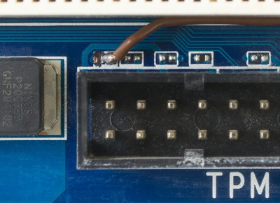
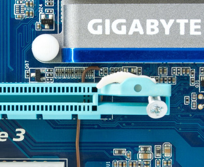
BTW I was able to milling off the copper trace jumper on my TPM pin 20 and then hooked a wire to LDRQ1# from PCH, so my MB Gigabyte GA-P67A-D3-B3 is ready for testing. I plan to send some batch to JLC...

Attachments

Gigabyte GA-P67-DS3-B3, Core i7-2600K @4,5GHz, 8GB DDR3, 128GB SSD, GTX970(GF7900GT), SB Audigy + YMF724F + DreamBlaster combo + LPC2ISA

Reply 128 of 456, by weedeewee

User metadata
Rank l33t
Rank
l33t
Duffman wrote on 2023-04-12, 16:21:
A bit of an odd question […]
Show full quote

A bit of an odd question

For boards that lack an LPC bus, could one of these debug cards be used to add one to a system?

Something like these?

https://www.ebay.com.au/itm/374588296387

https://www.ebay.com.au/itm/185843048118

fairly certain the answer to that question is No. The debug card uses either mini pci, mini pcie or lpc for the signals to display the debug codes.
It does not add an lpc interface for all I currently know.

Right to repair is fundamental. You own it, you're allowed to fix it.
How To Ask Questions The Smart Way
Do not ask Why !
https://www.vogonswiki.com/index.php/Serial_port

Reply 129 of 456, by Per Hansson

User metadata
Rank Newbie
Rank
Newbie
weedeewee wrote on 2023-04-12, 19:08:
Duffman wrote on 2023-04-12, 16:21:

A bit of an odd question

For boards that lack an LPC bus, could one of these debug cards be used to add one to a system?

fairly certain the answer to that question is No. The debug card uses either mini pci, mini pcie or lpc for the signals to display the debug codes.
It does not add an lpc interface for all I currently know.

Exactly correct!
That said it would be a nice addition to the PCB of the dISAppointment:
To be able to add your own Port 80H debug 7-segment LED.
I would also like to see a floppy header wink wink 😉
If not needed components could just be left out, but would be very nice to offer the option to have them 😀

Reply 131 of 456, by rasteri

User metadata
Rank Member
Rank
Member

To answer some FAQs -

1. Can I have multiple ISA slots? -- I'd recommend using a solution like this - Short on ISA slots? Try this. - I don't have any interest in modifying the disappointment board to add more slots, as then it likely wouldn't fit in a case.

2. Can I have power converters on board to eliminate the ATX splitter? -- If someone else wants to do the work then sure, but I am happy using the ATX splitter 😀

3. Floppy Connector? -- @RayeR has you covered - http://rayer.g6.cz/hardware/lpc_sio.htm

Reply 132 of 456, by Nexxen

User metadata
Rank Oldbie
Rank
Oldbie
LSS10999 wrote on 2023-04-08, 03:06:
I think AMD is, in some cases, simply not clear about which exact device (CPU/chipset) a given documentation is meant for, espec […]
Show full quote
rasteri wrote on 2023-04-06, 16:22:
RayeR wrote on 2023-04-06, 13:27:

There's no pin map for AM5 and Pin Description seems to be incomplete, no pin numbers. I don§t understand why AMD turned from open documentation to keep all secret.

In companies like AMD everything is secret by default. There's no real benefit to releasing pinouts, and I bet their legal team can think of 1000 bullshit ways it could bite them on the ass

I think AMD is, in some cases, simply not clear about which exact device (CPU/chipset) a given documentation is meant for, especially when it comes to present day hardware, by using only family and model numbers (codenames for chipsets). Additionally, they seem to document certain components only once unless there's a change somewhere, and it up to the audience to look for the exact one that mentioned the component in question.

(PS: According to some old news regarding the AMD 900 family chipset, the SB900 family southbridges were actually SB800 rebranded. If that's true then it explained why there were no databooks at all about SB900, since the old documents for SB800 would still be valid in this case, and there's no need for them to re-publish the same databooks.)

I did manage to find mentions about Ryzen's LPC controller (1022:790e) in some PPRs only after looking at several of them.

This one is for earlier Zen (17h), and this one is for later Zen (19h). They don't appear to differ much... You can find some other PPRs for some different models of those particular families, but they do not appear to contain sections about the FCH.

NOTE: There is a bit referring to LDRQ#1 in the FCH LPC PCI Config register (D14F3x078), but I couldn't find it on the AM4 pin map. Don't know if that other LDRQ# signal really exists...
EDIT: Nope. There's only one LDRQ# signal. The bit in question could be found in the fam19h PPR, but in the fam17h PPR the same bit was written as "reserved".

weedeewee wrote on 2023-04-07, 12:22:

Paul Daniels's OpenBoardview (free) / FlexBV

By the way... OpenBoardView cannot open fz files by default.

You need to look for a so-called decoding key yourself, and put it into the configuration file.
Do you happen to know where to find the key?

PC#1 Pentium 233 MMX - 98SE
PC#2 PIII-1Ghz - 98SE/W2K

Reply 133 of 456, by LSS10999

User metadata
Rank Oldbie
Rank
Oldbie
rasteri wrote on 2023-04-14, 11:24:

2. Can I have power converters on board to eliminate the ATX splitter? -- If someone else wants to do the work then sure, but I am happy using the ATX splitter 😀

I wonder if it is possible to use a small DC-ATX power module, that can be powered with an external 12V source (usually 5525 barrel, though PCIe 6-pin to 5525 converters exist).

However... a problem with this would be how to "turn on" the power module the way the power switch does... From the schematic it seems the PS_ON# is exposed via J4... so it may be possible to make it work by putting a jumper cap over it.

Nexxen wrote on 2023-04-14, 17:08:

Do you happen to know where to find the key?

I've found it. A little hint: You can't easily find it with Google for this. Use another search tool.

Reply 134 of 456, by Per Hansson

User metadata
Rank Newbie
Rank
Newbie
LSS10999 wrote on 2023-04-15, 04:14:
rasteri wrote on 2023-04-14, 11:24:

2. Can I have power converters on board to eliminate the ATX splitter? -- If someone else wants to do the work then sure, but I am happy using the ATX splitter 😀

I wonder if it is possible to use a small DC-ATX power module, that can be powered with an external 12V source (usually 5525 barrel, though PCIe 6-pin to 5525 converters exist).

However... a problem with this would be how to "turn on" the power module the way the power switch does... From the schematic it seems the PS_ON# is exposed via J4... so it may be possible to make it work by putting a jumper cap over it.

Certainly using a PicoPSU would work, and be a quite nice solution when powered from the systems main ATX supply.
To keep it running you only need a wire from PSON singal to ground, easy...
That said most only offer 0.1A or even 0.05A on the negative -12v rail like the PicoPSU-80 for example.
And they don't offer a negative -5v rail.
So due to their limited -12v using a LM7905 to produce it would not be recommended.
However a cheap solution would be a LM2662 that is an inverter that only needs a capacitor for its charge pump (no inductor required) prebuilt modules can be found on eBay.
A LM2776 would be a more modern and slightly more efficient solution, both are capable of 200mA.
But if anyway going down this path it would not be much to also add a LT1054 and now we can produce the negative -12v too at 100mA like the PicoPSU.
And then we would only need a regular Molex header on the board instead of the ATX header to make it all work, I think it would be a pretty nice solution 😀

Reply 135 of 456, by LSS10999

User metadata
Rank Oldbie
Rank
Oldbie
Per Hansson wrote on 2023-04-16, 11:10:
Certainly using a PicoPSU would work, and be a quite nice solution when powered from the systems main ATX supply. To keep it run […]
Show full quote
LSS10999 wrote on 2023-04-15, 04:14:
rasteri wrote on 2023-04-14, 11:24:

2. Can I have power converters on board to eliminate the ATX splitter? -- If someone else wants to do the work then sure, but I am happy using the ATX splitter 😀

I wonder if it is possible to use a small DC-ATX power module, that can be powered with an external 12V source (usually 5525 barrel, though PCIe 6-pin to 5525 converters exist).

However... a problem with this would be how to "turn on" the power module the way the power switch does... From the schematic it seems the PS_ON# is exposed via J4... so it may be possible to make it work by putting a jumper cap over it.

Certainly using a PicoPSU would work, and be a quite nice solution when powered from the systems main ATX supply.
To keep it running you only need a wire from PSON singal to ground, easy...
That said most only offer 0.1A or even 0.05A on the negative -12v rail like the PicoPSU-80 for example.
And they don't offer a negative -5v rail.
So due to their limited -12v using a LM7905 to produce it would not be recommended.
However a cheap solution would be a LM2662 that is an inverter that only needs a capacitor for its charge pump (no inductor required) prebuilt modules can be found on eBay.
A LM2776 would be a more modern and slightly more efficient solution, both are capable of 200mA.
But if anyway going down this path it would not be much to also add a LT1054 and now we can produce the negative -12v too at 100mA like the PicoPSU.
And then we would only need a regular Molex header on the board instead of the ATX header to make it all work, I think it would be a pretty nice solution 😀

The Fintek bridge needs 3.3V, although the ISA slot doesn't appear to need it. You may want to use a SATA header that actually includes the 5th (orange) 3.3V wire.

Reply 136 of 456, by RayeR

User metadata
Rank Oldbie
Rank
Oldbie

I was thinking about charge pump too but it has quite big vout ripple, not a problem for digital circuits but not good for analog, so maybe a -12v switched supply and -5v LDO would be better...

3.3v can be also easily generated by LDO from 5V, I think the bridge would not need much current from 3v3.

Gigabyte GA-P67-DS3-B3, Core i7-2600K @4,5GHz, 8GB DDR3, 128GB SSD, GTX970(GF7900GT), SB Audigy + YMF724F + DreamBlaster combo + LPC2ISA

Reply 137 of 456, by LSS10999

User metadata
Rank Oldbie
Rank
Oldbie

It seems the BOM is a bit vague about some parts.
- There are footprints for some 745C101 resistor arrays (R_Network08), but from the photo in the OP, a bunch of resistors were used instead. The resistance (ohms) of the individual resistors are too blurry to be determined from the photo so I'm not sure which to use, be it individual resistors, or actual resistor arrays.
- Is there a voltage rating recommendation for the capacitors used (such as the 10uF ones)? The BOM only specified the capacitance but no voltage rating.
- From the OP's photo there were some 5-band resistors soldered to some test points. Are these resistors necessary for operation, or just for testing?

Reply 138 of 456, by rasteri

User metadata
Rank Member
Rank
Member
LSS10999 wrote on 2023-04-17, 05:25:
It seems the BOM is a bit vague about some parts. - There are footprints for some 745C101 resistor arrays (R_Network08), but fro […]
Show full quote

It seems the BOM is a bit vague about some parts.
- There are footprints for some 745C101 resistor arrays (R_Network08), but from the photo in the OP, a bunch of resistors were used instead. The resistance (ohms) of the individual resistors are too blurry to be determined from the photo so I'm not sure which to use, be it individual resistors, or actual resistor arrays.
- Is there a voltage rating recommendation for the capacitors used (such as the 10uF ones)? The BOM only specified the capacitance but no voltage rating.
- From the OP's photo there were some 5-band resistors soldered to some test points. Are these resistors necessary for operation, or just for testing?

I'm using 4K7 resistors for the arrays, though I think anything up to about 10k should be fine too.
Voltage rating should be more than twice what the voltage of the line is, so I'd use 30v capacitors to catch everything.
And no, the extra discrete resistors aren't neccessary.

Last edited by rasteri on 2023-04-18, 10:05. Edited 2 times in total.

Reply 139 of 456, by LSS10999

User metadata
Rank Oldbie
Rank
Oldbie
rasteri wrote on 2023-04-17, 12:13:

I'm using 4K7 resistors for the arrays, though I think anything up to about 10k should be fine too.

I couldn't find the actual 745C101 but there are many other manufacturers making 1206x5 bussed resistor arrays of similar pinout that could be used.

I'm currently looking at the datasheet of YC358 resistor arrays which appears to match the footprint dimension, with YC358T having matching pinout of 745X101 (similar to 745C101 though different in shape, being convex rather than concave).