VOGONS


Reply 140 of 457, by Happyarch

User metadata
Rank Newbie
Rank
Newbie
rasteri wrote on 2023-04-14, 11:24:
To answer some FAQs - […]
Show full quote

To answer some FAQs -

1. Can I have multiple ISA slots? -- I'd recommend using a solution like this - Short on ISA slots? Try this. - I don't have any interest in modifying the disappointment board to add more slots, as then it likely wouldn't fit in a case.

2. Can I have power converters on board to eliminate the ATX splitter? -- If someone else wants to do the work then sure, but I am happy using the ATX splitter 😀

3. Floppy Connector? -- @RayeR has you covered - http://rayer.g6.cz/hardware/lpc_sio.htm

On a slightly off-topic note, I wonder if I could mod in IBM PS/2 keyboard and mouse support by connecting a secondary Super I/O as mentioned in the linked blog post, in the event the onboard Super I/O doesn't support IBM PS/2\is unknown if it does(I.E no keyboard controller onchip)?
One thing I'm worried about for the chips that we can't get datasheets on, is that they if they indeed do not have a keyboard controller(or do, and the manufacturer just isn't using it), and despite not using/even having that feature they may still lay claim to IRQ1 and 12 preventing the addition of one's own keyboard controller and/or mouse.
Reply 141 of 457, by RayeR

User metadata
Rank Oldbie
Rank
Oldbie

What superIO do you have? Most of them already contains two PS/2 ports. Your MB has any PS/2 on backpanel? My GB has only one. Some smarter manufacturers route both PS/2 to single miniDIN connector allows use Y-cable to split for both KB+mouse. But not GB, they was just too lazy to route 2 wires out so I had to do myself to added extra PS/2 connector tapped to superIO pins. There's a risk that MB designer could use unused PS/2 pins as GPIO for another purpose, you would need to check yourself if it's wired somewhere else.
In theory it should be possible to do it via 2nd super IO if properly configured. Problem is that such configuration would be done after boot by some DOS utility that is too late and you couldn't control your PC via KBD at boot time neither able to enter SETUP. Making option ROM with initcode may help but not for BIOS hotkeys because option ROMs are usually run somewhere at end of POST process. It would need heavier BIOS modding to enable KB support early enough...

Gigabyte GA-P67-DS3-B3, Core i7-2600K @4,5GHz, 8GB DDR3, 128GB SSD, GTX970(GF7900GT), SB Audigy + YMF724F + DreamBlaster combo + LPC2ISA

Reply 142 of 457, by LSS10999

User metadata
Rank Oldbie
Rank
Oldbie
RayeR wrote on 2023-04-18, 20:18:

What superIO do you have? Most of them already contains two PS/2 ports. Your MB has any PS/2 on backpanel? My GB has only one. Some smarter manufacturers route both PS/2 to single miniDIN connector allows use Y-cable to split for both KB+mouse. But not GB, they was just too lazy to route 2 wires out so I had to do myself to added extra PS/2 connector tapped to superIO pins. There's a risk that MB designer could use unused PS/2 pins as GPIO for another purpose, you would need to check yourself if it's wired somewhere else.
In theory it should be possible to do it via 2nd super IO if properly configured. Problem is that such configuration would be done after boot by some DOS utility that is too late and you couldn't control your PC via KBD at boot time neither able to enter SETUP. Making option ROM with initcode may help but not for BIOS hotkeys because option ROMs are usually run somewhere at end of POST process. It would need heavier BIOS modding to enable KB support early enough...

Does any other manufacturer support PS/2 Y-cable? So far I only know ASRock actively supports it through a BIOS option and it indeed works with some such cables.

Though honestly if your motherboard has only one PS/2 port then use it for mouse whenever possible, as keyboards are more likely to work out-of-box over USB than mouse when it comes to legacy USB support.

Reply 143 of 457, by Windows98_guy

User metadata
Rank Newbie
Rank
Newbie

Hi

I have an ASRock h61m/u3s3 motherboard that does have a TPM1 connector, but it needs to be soldered on the board.

However the problem is that the manual doesn't mention having a TPM and as a result i don't know the pinout. Any ideas where i can get information on the pinout of this motherboard?

Reply 144 of 457, by iamspamiam

User metadata
Rank Newbie
Rank
Newbie

This is rather interesting and is another rabbit-hole for ISA connectivity I’ve gone down.

I’ve been digging around and it seems LDRQ# is the issue for most motherboards I’ve only found some Supermicro boards that put it on the LPC header.
I managed to find some boardviews (a weird rabbit-hole I’ve never encountered before)and been checking AM4 options and not found anything so far. Pretty much every board I’ve looked at LDRQ only connects to the super IO chip or is unconnected. This is also trickier as manufacturers have switched to SPI for the TPM module.

Of interest to is the ASUS PRO A520M which has some of the LPC bus on a debug header, but I’ve not found a board view to see whether the SERIRQ, PWDN#, and LDRQ# are accessible.

It may be worth trying to catalogue any motherboards that this project could work with.

Could this project be used to connect a PCI sound card with a SB-LINK connector to the LPC bus?

Reply 145 of 457, by LSS10999

User metadata
Rank Oldbie
Rank
Oldbie
iamspamiam wrote on 2023-04-19, 17:57:
This is rather interesting and is another rabbit-hole for ISA connectivity I’ve gone down. […]
Show full quote

This is rather interesting and is another rabbit-hole for ISA connectivity I’ve gone down.

I’ve been digging around and it seems LDRQ# is the issue for most motherboards I’ve only found some Supermicro boards that put it on the LPC header.
I managed to find some boardviews (a weird rabbit-hole I’ve never encountered before)and been checking AM4 options and not found anything so far. Pretty much every board I’ve looked at LDRQ only connects to the super IO chip or is unconnected. This is also trickier as manufacturers have switched to SPI for the TPM module.

Of interest to is the ASUS PRO A520M which has some of the LPC bus on a debug header, but I’ve not found a board view to see whether the SERIRQ, PWDN#, and LDRQ# are accessible.

It may be worth trying to catalogue any motherboards that this project could work with.

Could this project be used to connect a PCI sound card with a SB-LINK connector to the LPC bus?

SB-Link is for PC-PCI. I think that thing is purely a PCI technique and has nothing to do with LPC. It's also used by PCI-ISA bridges (like IT8888) to provide full ISA capability including DMA.

Sadly PC-PCI was removed since ICH6 and I'm not sure if other vendors ever supported PC-PCI at some point. Without PC-PCI the PCI-ISA bridge cannot provide DMA so only FM synth will work, which is the case of most known ISA-equipped motherboards on the market that use ICH6 and later.

Considering the circumstances of the boards already available on the market, a boardview is definitely required if you want to know how to access your board's LDRQ# signal.

PS: A side note. Some LPC SuperIO chips even had its own MPU-401 UART which seems to operate independently from sound cards (discrete or onboard). I wonder if it's theoretically possible to make SuperIO controllers that include more stuffs, such as Sound Blaster compatible DSP core (as well as FM cores), if they could be implemented compact enough.

EDIT: It seems ASUS Pro A520M/B550M you mentioned are indeed worth looking into if the boardview's available. It indeed has the LPC bus exposed for attaching a debug card, but it seems to be using a 24MHz clock (CK_24M_LPC). Still need to look for the LDRQ# signal, though. It also doesn't have PCICLK, PCIRST#, SERIRQ and PWRDN#. Don't know which of these are really required... (just SERIRQ maybe?).

Reply 146 of 457, by rasteri

User metadata
Rank Member
Rank
Member
LSS10999 wrote on 2023-04-20, 01:37:

It also doesn't have PCICLK, PCIRST#, SERIRQ and PWRDN#. Don't know which of these are really required... (just SERIRQ maybe?).

You'll definitely need PCICLK, PCIRST and SERIRQ. Dunno what that 24MHz clock line is for but PCICLK is supposed to be 33MHz

Reply 147 of 457, by rasteri

User metadata
Rank Member
Rank
Member

The ISA protocol allows for memory-mapped transactions to components placed on the bus. In order to support these transactions it is, therefore, necessary to support memory-mapped transaction on the LPC bus.
The LPC specification specifies that such transactions are supported on the LPC bus. Indeed, on all I/O Controller Hubs up to and including ICH5 support these transactions. From ICH6 onwards, however, support for these transactions has been removed. As a result, it is not possible to support ISA memory mapped transactions on an Intel® Express chipset.

I suppose that's why I've never got graphics cards to work. Might have to get hold of an ICH5 motherboard. (or maybe AMD still supports memory mapped transactions)

Reply 149 of 457, by LSS10999

User metadata
Rank Oldbie
Rank
Oldbie
Shadow Lord wrote on 2023-04-21, 03:46:

Two questions:

1. Are you limited to one slot? Or can you have multiple ISA slots (e.g. one for sound and one for fdc)?

2. Does it support FDCs?

These questions have been answered already. See here.

As for the second question... since some SuperIO chips also have FDC (although they may not actually expose connector for them), you probably need to do some detailed configurations to make sure SuperIO won't get in your way when connecting a FDC.

Reply 150 of 457, by Shadow Lord

User metadata
Rank Newbie
Rank
Newbie
LSS10999 wrote on 2023-04-21, 06:04:

These questions have been answered already. See here.

As for the second question... since some SuperIO chips also have FDC (although they may not actually expose connector for them), you probably need to do some detailed configurations to make sure SuperIO won't get in your way when connecting a FDC.

Thanks. Thought that may be the case but the topis is at eight pages and growing. Perhaps a stick FAQ at the top would help alleviate the commonly aske/re-asked questions?

Interesting on the FDC. That makes it much harder because you would have to either have a board without (hidden) FDC support or have a way to disable it. Would have been nice if I could just throw in something like a compaticard in there and be good to go.

What we really need (and I am sure someone will one day produce) is a system on a card i.e. all the HW that is needed for a vintage 386 or 486 would be on an add in board and the only thing that would happen is that KB/mouse input and video output would be routed to the main system. The card could have connectors for FDC and for an optional external backplane. Of course by then you might as well just get a vintage system.... 🤣.

Reply 151 of 457, by LSS10999

User metadata
Rank Oldbie
Rank
Oldbie
rasteri wrote on 2023-04-20, 11:04:

You'll definitely need PCICLK, PCIRST and SERIRQ. Dunno what that 24MHz clock line is for but PCICLK is supposed to be 33MHz

Guess it's not going to be easy for these boards then... requiring at least 4 wires, but still better than nothing.

So in the end AMD 400 series is the practical end-of-line for LPC-based TPM header. Pretty much all AMD 500 series boards have switched to SPI for TPM despite LDRQ# is still there.

Reply 152 of 457, by rasz_pl

User metadata
Rank l33t
Rank
l33t

I was just watching PR02X Dell E-port Plus II docking station teardown https://www.youtube.com/watch?v=Wvyp0teLPTg
and that thing has LPC47N237 inside, close enough: https://pdf1.alldatasheet.com/datasheet-pdf/v … C47N227_07.html
matching laptop diagram https://forum.laboneinside.com/viewtopic.php?t=6624
so there is huge potential a ton of docking stations are connected with laptops from ~2010 with LPC

Open Source AT&T Globalyst/NCR/FIC 486-GAC-2 proprietary Cache Module reproduction

Reply 153 of 457, by rasteri

User metadata
Rank Member
Rank
Member
rasz_pl wrote on 2023-04-24, 03:15:
I was just watching PR02X Dell E-port Plus II docking station teardown https://www.youtube.com/watch?v=Wvyp0teLPTg and that thin […]
Show full quote

I was just watching PR02X Dell E-port Plus II docking station teardown https://www.youtube.com/watch?v=Wvyp0teLPTg
and that thing has LPC47N237 inside, close enough: https://pdf1.alldatasheet.com/datasheet-pdf/v … C47N227_07.html
matching laptop diagram https://forum.laboneinside.com/viewtopic.php?t=6624
so there is huge potential a ton of docking stations are connected with laptops from ~2010 with LPC

Yeah I noticed that some docking stations had LPC. I also have a E-Port plus II I could experiment with. I can't imagine used dell laptops are expensive...

I had some issues with a Latitude D630 - it doesn't route proper LPC to its docking station (a much older model). Then when I manualy soldered wires to test points on the motherboard, it detected the Fintek bridge but unisound couldn't detect any cards. Presumably some kind of resource conflict, I know laptops have a lot of extra crap in them

Reply 154 of 457, by myne

User metadata
Rank Member
Rank
Member

Fascinating project.

I see things like this, and I want to email one of those chinaboard companies to make an idea I've had for a while.

Basically, it's an SBC on a backwards PCIE card.
Ie, the cpu, chipset superio and everything you'd normally have on a mini-itx board except the pcie slot is an edge connector.

Then the "Motherboard" is just a backplane that fits in the standard AT/ATX/EATX expansion card slots.

In my imagination, the processor would take the top 2-3 slots and face "up", there'd be a PCI-E 1-4x slot next to that for sound/whatever, and a 16x slot for your GPU. The "CPU card" would vent out the back, and only have some of the most basic connectivity taking 1 slot. Eg USB, Video, LAN.
Since the "CPU card" and GPU would be facing opposite directions, and have a 1 card spacer between them, they could be built to have their separate thermal zones.

But that's just one idea. With projects like this dISAppointment, and the others I see here, the 4-6 remaining slots could be AGP, PCI or ISA with the appropriate bridge chips on the relatively simple backplane.

Interestingly, since ISA and PCI/PCIE are facing opposite directions, and historically they can share a riser slot (not simultaneously), you could build a board with an ISA slot sharing the 4x PCIE riser between the CPU/GPU.

EG:
Slots 1-3 = CPU
Slot 4= ISA/PCI-E4x
Slot 5-7=GPU (16x PCIE)
* Note: There's nothing stopping you from using slots 6 and 7, but GPU trends suggest they're not really usable in practice. This board could theoretically run DOS with a genuine SB16 and reboot into a modern OS.

Or, with a different designed backplane and the same "CPU card", you could build a very compact "ultimate DOS/9x" machine.

Slots 1-3 = CPU
Slot 4= AGP/ISA (Geforce?)
Slot 5= PCI/ISA (SB16?)
Slot 6= PCI/ISA (Voodoo2?)
Slot 7= PCI/ISA (Voodoo2?)
* Note: slots 4/5 chosen for Geforce/SB16 to add just that extra bit of clearance for airflow between the cards.

Or with the same backplane, you can run your ancient industrial workhorse with up to 4x ISA cards.
Different backplane, and a more custom case, sky's the limit.

Intel did TRY and do something almost exactly like this recently.
https://www.anandtech.com/show/14953/the-pc-o … ristine-to-life
They made one horrible mistake though IMO.
The card faces the same direction as the GPU. If it was backwards (and had a full spec'd TPM header), it'd be perfect.

Reply 155 of 457, by myne

User metadata
Rank Member
Rank
Member
Windows98_guy wrote on 2023-04-19, 08:17:

Hi

I have an ASRock h61m/u3s3 motherboard that does have a TPM1 connector, but it needs to be soldered on the board.

However the problem is that the manual doesn't mention having a TPM and as a result i don't know the pinout. Any ideas where i can get information on the pinout of this motherboard?

I can't link to things that aren't totally above board here, but if you Google "Asrock H61M/U3S3 Boardview" you'll be on the right track.

Reply 156 of 457, by myne

User metadata
Rank Member
Rank
Member

I might just add another note. Out of curiosity I compared a B365 board and a Z370.

The 1/2/300 series aren't meant to have LDRQ.

But... maybe the humans at Intel are human, and don't so much delete features as... stop documenting/supporting them.

And maybe board designers are lazy, and don't update their pin definitions when the basic chipset design is more or less an iterative evolution of the same thing rather than a revolutionary design.

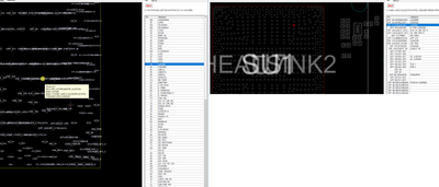
So, this is the B365 and Z370 chipset with the Superio nets.

IF the above assumptions about human laziness are correct, then LDRQ#0 may still exist on both of those chipsets as GPP_A7 and logically, the same chipset straps documented in the 9 series chipset could enable it. In the 9 series chipset LDRQ#1 is configurable as GPIO instead. It might be possible that LDRQ#0 is missing but LDRQ#1 still works, and could be configured instead. Would that work?

Does this mean anything to anyone?

Bus Master Device Mapping and START Fields
Bus Masters must have a unique START field. In the case of the PCH that supports two LPC bus masters, it drives 0010 for the START field for grants to Bus Master 0 (requested using LDRQ0#) and 0011 for grants to Bus Master 1 (requested using LDRQ1#.). Thus, no registers are needed to configure the START fields for a particular bus master.

https://www.intel.com.au/content/dam/www/publ … h-datasheet.pdf

Attachments

  • b365-z370.png
    Filename
    b365-z370.png
    File size
    331.07 KiB
    Views
    1553 views
    File license
    Public domain

Reply 157 of 457, by rasteri

User metadata
Rank Member
Rank
Member
myne wrote on 2023-04-26, 10:46:

IF the above assumptions about human laziness are correct, then LDRQ#0 may still exist on both of those chipsets as GPP_A7 and logically, the same chipset straps documented in the 9 series chipset could enable it. In the 9 series chipset LDRQ#1 is configurable as GPIO instead. It might be possible that LDRQ#0 is missing but LDRQ#1 still works, and could be configured instead. Would that work?

It's possible I suppose. I think it's unlikely though so I'm not gonna spend the time trying it 😀 If you have a 100 series motherboard then by all means give it a go.

Does this mean anything to anyone? […]
Show full quote

Does this mean anything to anyone?

Bus Master Device Mapping and START Fields
Bus Masters must have a unique START field. In the case of the PCH that supports two LPC bus masters, it drives 0010 for the START field for grants to Bus Master 0 (requested using LDRQ0#) and 0011 for grants to Bus Master 1 (requested using LDRQ1#.). Thus, no registers are needed to configure the START fields for a particular bus master.

https://www.intel.com.au/content/dam/www/publ … h-datasheet.pdf

Bus mastering isn't terribly useful for what we need to do, typically it was just used for stuff like hard drive controllers

Reply 159 of 457, by Happyarch

User metadata
Rank Newbie
Rank
Newbie
RayeR wrote on 2023-04-18, 20:18:

What superIO do you have? Most of them already contains two PS/2 ports. Your MB has any PS/2 on backpanel? My GB has only one. Some smarter manufacturers route both PS/2 to single miniDIN connector allows use Y-cable to split for both KB+mouse. But not GB, they was just too lazy to route 2 wires out so I had to do myself to added extra PS/2 connector tapped to superIO pins. There's a risk that MB designer could use unused PS/2 pins as GPIO for another purpose, you would need to check yourself if it's wired somewhere else.
In theory it should be possible to do it via 2nd super IO if properly configured. Problem is that such configuration would be done after boot by some DOS utility that is too late and you couldn't control your PC via KBD at boot time neither able to enter SETUP. Making option ROM with initcode may help but not for BIOS hotkeys because option ROMs are usually run somewhere at end of POST process. It would need heavier BIOS modding to enable KB support early enough...

No specific chip yet, but I was speculating on it because I was building a workstation with a large ammount of PCI-E lanes, and due to TRX40 boards and Threadripper 3000 being mostly out of stock, or more expensive than Threadripper 5000 and/or sWRX80 I'm having to get one of those boards, but none of the sWRX80 boards have PS/2 ports, atleast already on the board, now if the Super I/O supports it is another question.

Currently I'm looking at a Supermicro M12SWA-TF, it says in the manual that the Super I/O is the same chip as the BMC controller, but I know this just isn't correct due to the Aspeed chip on there not providing Super I/O functions and that on high resolution photos of the board you can clearly spot a Super I/O chip from Nuvoton near the BMC. I can't quite make it out but I think it's the NCT6796D, if so that's good because I can actually get datasheets for that one, which I can confirm does have a keyboard controller, although it can be disabled from the looks of it, which they may have done considering they didn't offer PS/2 ports onboard hooked to it.