VOGONS


IBM PS/1 2155-593 Restoration

Topic actions

First post, by appiah4

User metadata
Rank l33t++
Rank
l33t++

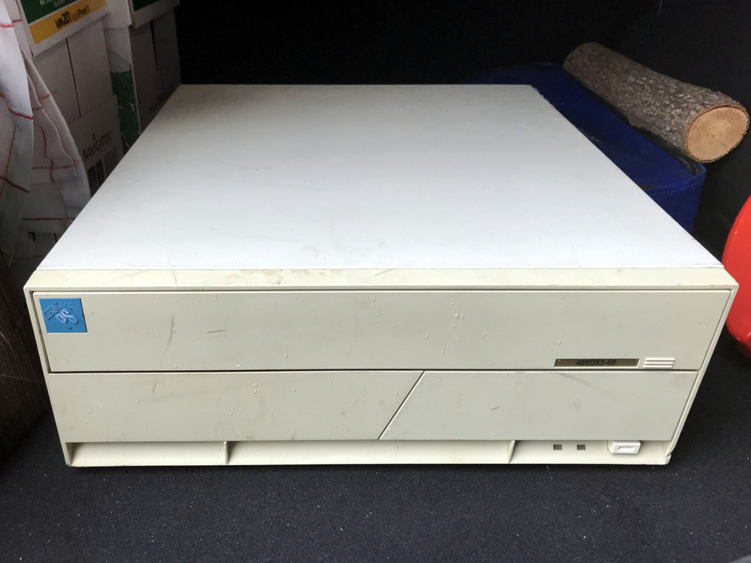
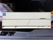
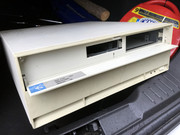
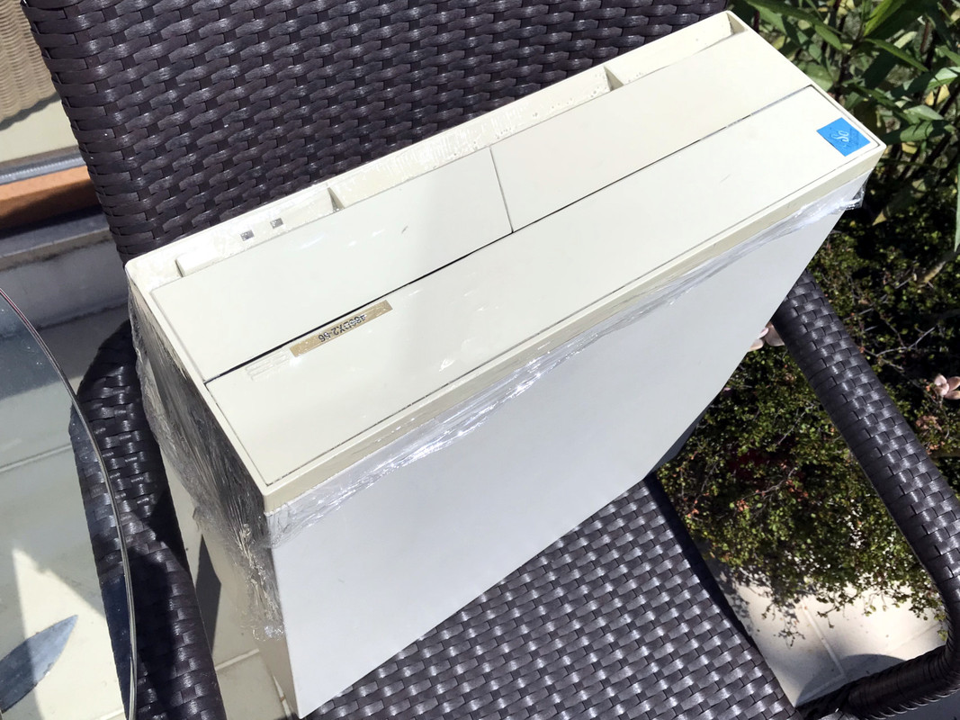
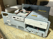
Earlier in the year, just before the pandemic woes struck, I saw an IBM case in a recycler's inventory. He usually sells me motherboards, CPUs and expansion cards he salvages from PCs and I am rarely interested in the cases as they are often in terrible shape by the time they reach him, but this one caught my eye. I had no idea what (if anything at all) was in it, but I had it shipped to me at a very modest cost. This is what it looked like when I received it:

IBM-PS1-2155-593-Original-State-01.jpg

IBM-PS1-2155-593-Original-State-02.jpg IBM-PS1-2155-593-Original-State-03.jpg IBM-PS1-2155-593-Original-State-05.jpg

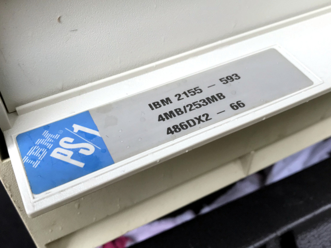
It is from November 1993 and actually has a fairly neat configuration, top of the line for the IBM PS/1 products unless I am mistaken:

IBM-PS1-2155-593-Original-State-04.jpg

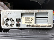
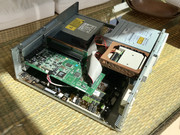
Upon opening the case up, I found that it actually had most of the components, as well as having been upgraded to 16MB of RAM. It was, however, missing the 3.5" Floppy/HDD drive cage and case spine part (which may have very well been missing from the factory as some of these boxes apparently shipped with 5.25" combi floppies instead) and the hard drive. Everything else, including the riser card, was present. I decided it would be worth salvaging and restoring, so many months later I got down to it.

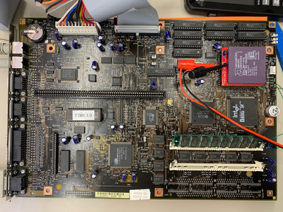
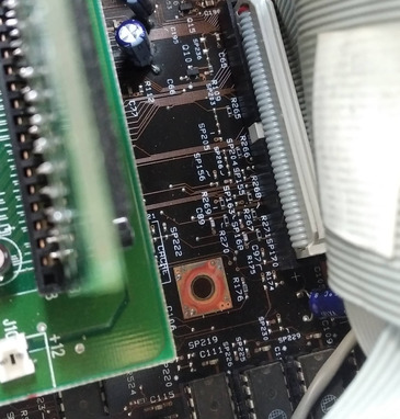
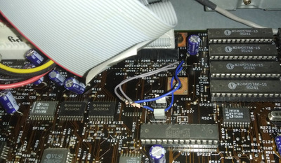
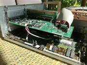
First order of business was disassembly and a deep cleaning as the thing has apparently been a home to many different kinds of pests. Unfortunately I do not have any photos of the mess it was before I got to work, but this is how the motherboard ended up:

IBM-PS1-2155-593-Motherboard-01.jpg

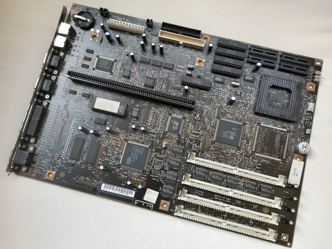
Quite a beautiful motherboard if you ask me. Next up, it was time for some retrobrighting:

IBM-PS1-2155-593-Retrobright-01.jpg

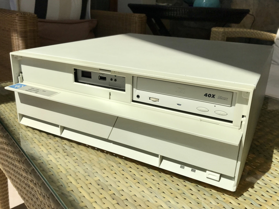
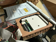
I replaced the missing drive cage to a 3D printed plastic part which did the job quite well. Instead of a real floppy drive, I opted for an OLED and buzzer modded Flash-Floppy GOTEK. I replaced the Hard Drive with a 512MB CF-IDE onto which I copied over a 1994 factory image from a US PS/1 Multimedia onto it. I also added a Samsung 40x CD-ROM and a Creative Sound Blaster 16 CT2290 to the system.

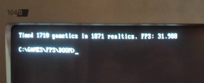
It turned out rather well, if I may say so myself..

IBM-PS1-2155-593-01.jpg

IBM-PS1-2155-593-02.jpg IBM-PS1-2155-593-03.jpg IBM-PS1-2155-593-04.jpg IBM-PS1-2155-593-05.jpg IBM-PS1-2155-593-06.jpg

Retronautics: A digital gallery of my retro computers, hardware and projects.

Reply 1 of 29, by tman_sys

User metadata
Rank Newbie
Rank
Newbie

Wow, so good to see this model! This was the same PS/1 that I purchased from Circuit City back in late September of '94 as a birthday gift to myself. It was my very first PC and helped me launch my IT career. What great memories of this fine machine. Sadly, in 2015 I lost the entire system in a tragic house fire. What I wouldn't give to get my hands on this model again...hint hint 😀

Reply 2 of 29, by Intel486dx33

User metadata
Rank l33t
Rank
l33t

There was many versions of the IBM PS/1. It all depended on what store you purchased it form.
There was at least 5 different versions.
They all had different motherboards.
Some came with a 486sx-25 or 33 onboard with an Intel Overdrive socket and then there are those that came with a
486dx-50 like yours with a standard CPU socket.

These are my favorite 486 computers because they look so clean and simple with all the covers closed.
Also the original IBM install came with allot of tools and batch files for maintaining the computer
For ease of use. That is what set IBM apart from everyone else. Not just that they had the best hardware for there time.
But ease of use setup and menu system included with there operating system.

I use the 1994 VLB multimedia edition.
https://ps1stuff.wordpress.com/download/downl … -for-type-2133/

Also the “Multimedia edition” came with the following specs.
486dx2-50
8mb ram
64kb motherboard cache
2x Panasonic CDROM
Sound blaster CT2950
270mb hard drive.

This is the type of configuration computer manufactures where selling back in 1993/94

But I would not worry about motherboard cache or CPU upgrade.
It’s a 486 and NOT a Pentium CPU computer.
The only CPU upgrade that will make any difference is the Pentium Overdrive 83mhz.
But these are very expensive and rare to day.
Better to build a Pentium computer for that.

I would keep it original as possible as a 486dx-50 computer.

Last edited by Intel486dx33 on 2022-06-28, 11:57. Edited 2 times in total.

Reply 3 of 29, by tman_sys

User metadata
Rank Newbie
Rank
Newbie

Agreed. This system had a lot of bells and whistles which is why it made for a great first computer for me. I cannot even begin to tell you how much I learned from breaking the software and using it's native repair tools to restore. Moreover were the countless upgrades I put into my old system.

I had the Multimedia version as I distinctly remember the logo sticker it had on the top of the case just above the CD-ROM bay. Similar logo that is on the Multimedia CD-ROM. Don't see too may of those these days but I would sure scoop one up in a heartbeat.

I landed an alternate model a month or so ago, which will have to do for now to cure the itch. I'm with you...I just want it all stock with DOS/Windows 3.1 the way it came from Circuit City when i bought it.

Cheers!

Reply 4 of 29, by retroegde

User metadata
Rank Newbie
Rank
Newbie

I know the original post is coming up on 2 years but I just got an IBM 2155a-c24 with the same motherboard. The screenshots of this restore have been helpful. I have a question about the 486dx processor. How many pins does it have? My computer has an SX chip soldered to the board with that socket empty for an upgrade. That socket is 238 pins and processors with that many pins seem to be difficult to find. Does your processor have the standard 168 pins?

Reply 5 of 29, by appiah4

User metadata
Rank l33t++
Rank
l33t++

It was a standard 168 pin. Thebextra pins are for Pentium OD processors.

Retronautics: A digital gallery of my retro computers, hardware and projects.

Reply 6 of 29, by Intel486dx33

User metadata
Rank l33t
Rank
l33t

I think the Intel Overdrive CPU ( 50, 75 and 100mhz ) with 169 pins were made for this computer in mind.
I think the Intel Overdrive 75 and 100 are DX4.
Either of those would be a nice upgrade.

Reply 7 of 29, by retroegde

User metadata
Rank Newbie
Rank
Newbie

I went and pulled the trigger and bought an Am5x86-P75 AMD AM486DX5-133W16BHC. 169-pin chip with the voltage regulator to convert 5v to 3.45v. Plugged it in and worked perfectly. Crazy seeing 133mhz on this IBM PC. This thread has all the info you need for this chip info about "Am5x86-P75 AMD AM486DX5-133W16BHC Chip". Thank you for the responses to confirm 169-pin is what I needed.

Reply 8 of 29, by epictronics

User metadata
Rank Newbie
Rank
Newbie

I'm working on a PS/1 2168 and the board looks identical to the board in this thread.
However, my board is set to 25Mhz and there doesn't seem to be a jumper to change it to 33Mhz.
The only difference I can spot int the picture is that the board in this thread has a jumper connected to j27
That's kind'a odd, because j27 is marked "speaker"
Does anyone have any ideas on what could be worth trying to get it up to 33Mhz?
Or maybe take a high res image of the board? I can'd quite make out the text on the chips or crystal in the picture.
Any advice appreciated, thanks!

Attachments

YouTube

Reply 9 of 29, by Thermalwrong

User metadata
Rank Oldbie
Rank
Oldbie
epictronics wrote on 2023-05-12, 07:44:
I'm working on a PS/1 2168 and the board looks identical to the board in this thread. However, my board is set to 25Mhz and ther […]
Show full quote

I'm working on a PS/1 2168 and the board looks identical to the board in this thread.
However, my board is set to 25Mhz and there doesn't seem to be a jumper to change it to 33Mhz.
The only difference I can spot int the picture is that the board in this thread has a jumper connected to j27
That's kind'a odd, because j27 is marked "speaker"
Does anyone have any ideas on what could be worth trying to get it up to 33Mhz?
Or maybe take a high res image of the board? I can'd quite make out the text on the chips or crystal in the picture.
Any advice appreciated, thanks!

Hey there, just watched your video and I'm interested in this. Looks like the only difference is the CPU attached to yours that's not attached to the one in this thread.
It seems pretty silly that they'd hard-wire the bus speed so there must be some way to change it but maybe only during production - I'm wondering if they left some way to control that with some unconnected solder pads like I've seen for setting FSB and multiplier on laptops and things.

Could you get a closer in shot of the area around the 14.3MHz crystal without the CPU power wires in the way? That's where the PLL is so it makes sense to look there first.
It looks like the SPxxx things are just un-used pads and it doesn't appear that parts go there, but playing spot the difference between your board and the one in this thread - looks like there's a difference at R174 / R175 / R176 by the IDE socket. It could be worth checking if any of those link to the PLL and what the resistor values are.

Reply 10 of 29, by epictronics

User metadata
Rank Newbie
Rank
Newbie
Thermalwrong wrote on 2023-05-13, 22:04:
epictronics wrote on 2023-05-12, 07:44:

I'm working on a PS/1 2168 and the board looks identical to the board in this thread.
...

Could you get a closer in shot of the area around the 14.3MHz crystal without the CPU power wires in the way? That's where the PLL is so it makes sense to look there first.
It looks like the SPxxx things are just un-used pads and it doesn't appear that parts go there, but playing spot the difference between your board and the one in this thread - looks like there's a difference at R174 / R175 / R176 by the IDE socket. It could be worth checking if any of those link to the PLL and what the resistor values are.

Oh, silly me to leave the wires covering up the most interesting part 🤣
Let's try again...
It would be very useful with a close-up of the the 2155 board too if anyone reading this has one
Thanks

Attachments

  • IMG_2742.jpeg
    Filename
    IMG_2742.jpeg
    File size
    1.97 MiB
    Views
    1814 views
    File license
    Public domain

YouTube

Reply 11 of 29, by Thermalwrong

User metadata
Rank Oldbie
Rank
Oldbie

Thanks, that helps - check this out:

tracing-imisc418.jpg
Filename
tracing-imisc418.jpg
File size
1005.18 KiB
Views
1803 views
File license
CC-BY-4.0

This is only my guess at the moment but the lines match up too well. I think the R174 - R175 - R176 are the solder/component jumpers to specify the PLL frequency. They are like this between the two boards:
-----PS/1 2155-593 DX33 ----- Your 25MHz PS/1
R174 ----- Populated ------- Not Populated
R175 ----- Populated ------- Not Populated
R176 --- Not Populated -------- Populated
Have a read of the datasheet for the PLL here: https://www.datasheetarchive.com/IMISC418%20-datasheet.html
The S0 / S1 / S2 pins each have pull up resistors so if they are disconnected, I guess their value should be a 1 digitally:

pll-pinout.png
Filename
pll-pinout.png
File size
26.53 KiB
Views
1803 views
File license
CC-BY-4.0
pll-frequency-table.png
Filename
pll-frequency-table.png
File size
100.59 KiB
Views
1803 views
File license
CC-BY-4.0

The frequency table shows that 0-1-1 gives 50mhz and 1-0-0 gives 66mhz.

Given how well everything lines up, I think that the other side of the R174/5/6 pad goes to Ground. Meaning that if the Resistor pad is populated then it's pulled to Ground giving a 0 digitally - you should be able to change the frequency to 33 or higher by changing which pads are populated. It would be helpful to know the resistor value as well, should be quite a low value.
Hope that helps 😀

Last edited by Thermalwrong on 2023-05-14, 15:10. Edited 1 time in total.

Reply 12 of 29, by Thermalwrong

User metadata
Rank Oldbie
Rank
Oldbie

Forgot to annotate this bit:
red line: S2
green line: S1
blue line: S0

Looks like you may want to upgrade the SRAM as well if you want to go for 33mhz bus speed or higher.

Reply 13 of 29, by epictronics

User metadata
Rank Newbie
Rank
Newbie
Thermalwrong wrote on 2023-05-13, 23:08:

This is only my guess at the moment but the lines match up too well. I think the R174 - R175 - R176 are the solder/component jumpers to specify the PLL frequency.

You have a sharp eye!
The board is on the bench, let's give this a try : )
Thanks!

YouTube

Reply 16 of 29, by theelf

User metadata
Rank Oldbie
Rank
Oldbie

Hi guys, very interesting thread, i have a tower IBM 2168-552, 25mhz locked, take a picture too

R176 Populated
R174 & 75 NOT

I have a overdrive DX4/75mhz (3x25) and i will LOVE to overclock to 100mhz (3x33)

IBM.jpg
Filename
IBM.jpg
File size
286.87 KiB
Views
1604 views
File license
Public domain

Reply 17 of 29, by epictronics

User metadata
Rank Newbie
Rank
Newbie
theelf wrote on 2023-05-18, 18:18:
Hi guys, very interesting thread, i have a tower IBM 2168-552, 25mhz locked, take a picture too […]
Show full quote

Hi guys, very interesting thread, i have a tower IBM 2168-552, 25mhz locked, take a picture too

R176 Populated
R174 & 75 NOT

I have a overdrive DX4/75mhz (3x25) and i will LOVE to overclock to 100mhz (3x33)

IBM.jpg

I just finished the video about this hack. It will go live on Saturday : )

YouTube

Reply 18 of 29, by theelf

User metadata
Rank Oldbie
Rank
Oldbie
epictronics wrote on 2023-05-18, 21:05:
theelf wrote on 2023-05-18, 18:18:
Hi guys, very interesting thread, i have a tower IBM 2168-552, 25mhz locked, take a picture too […]
Show full quote

Hi guys, very interesting thread, i have a tower IBM 2168-552, 25mhz locked, take a picture too

R176 Populated
R174 & 75 NOT

I have a overdrive DX4/75mhz (3x25) and i will LOVE to overclock to 100mhz (3x33)

IBM.jpg

I just finished the video about this hack. It will go live on Saturday : )

Thanks, i watched the video, and decide to do

In my case, i dont have a good soldering iron, then i needed to improvise, decide to solder cables, and the resistors to the cables, less chances to damage motherboard

soldering.jpg
Filename
soldering.jpg
File size
255.95 KiB
Views
1497 views
File license
Public domain

Lucky me, the DX4 overdrive boot without trouble, get more hot than before, but looks like not too much.... maybe better a fan?

Ok, benchmarks... the difference is HUGE!!!!

BEFORE

1.jpg
Filename
1.jpg
File size
13.98 KiB
Views
1497 views
File license
Public domain
2.jpg
Filename
2.jpg
File size
79.65 KiB
Views
1497 views
File license
Public domain

AFTER

3.jpg
Filename
3.jpg
File size
15.68 KiB
Views
1497 views
File license
Public domain
4.jpg
Filename
4.jpg
File size
108.18 KiB
Views
1497 views
File license
Public domain

AMAZING!!! i want to say thank you to all of you

Thermalwrong wrote on 2023-05-13, 23:08:
Thanks, that helps - check this out: tracing-imisc418.jpg […]
Show full quote

Thanks, that helps - check this out:
tracing-imisc418.jpg

This is only my guess at the moment but the lines match up too well. I think the R174 - R175 - R176 are the solder/component jumpers to specify the PLL frequency. They are like this between the two boards:
-----PS/1 2155-593 DX33 ----- Your 25MHz PS/1
R174 ----- Populated ------- Not Populated
R175 ----- Populated ------- Not Populated
R176 --- Not Populated -------- Populated
Have a read of the datasheet for the PLL here: https://www.datasheetarchive.com/IMISC418%20-datasheet.html
The S0 / S1 / S2 pins each have pull up resistors so if they are disconnected, I guess their value should be a 1 digitally:
pll-pinout.png
pll-frequency-table.png
The frequency table shows that 0-1-1 gives 50mhz and 1-0-0 gives 66mhz.

Given how well everything lines up, I think that the other side of the R174/5/6 pad goes to Ground. Meaning that if the Resistor pad is populated then it's pulled to Ground giving a 0 digitally - you should be able to change the frequency to 33 or higher by changing which pads are populated. It would be helpful to know the resistor value as well, should be quite a low value.
Hope that helps 😀

Thermalwrong thanks a lot for all hel to this thread

Reply 19 of 29, by Thermalwrong

User metadata
Rank Oldbie
Rank
Oldbie

Just watched the video too, thanks for the mention on there epictronics 😀
It was a very well put together video and it's great that this is working in the way that I guessed from the pictures - an educated guess though, I've done similar things with my Toshiba T2130CS laptop.

theelf: That's a pretty good way of getting around that actually. Potentially you could connect up a 3-position DIP switch or jumpers to the S0/S1/S2 lines since that's what the datasheet shows, maybe IBM put resistors on there for a reason but it shouldn't be necessary since it's only setting some jumpers really - the only thing that's necessary is for the resistance to ground to be lower than the resistance on the pull-up resistors that are internal to the PLL