VOGONS


Reply 420 of 907, by NachtRave

User metadata
Rank Member
Rank
Member
sofakng wrote on 2022-06-06, 19:59:
Does anybody have any ideas on how to add a real OPL2/OPL3 chip to this box? […]
Show full quote

Does anybody have any ideas on how to add a real OPL2/OPL3 chip to this box?

For example, there is an OPL2LPT adapter that outputs OPL2 over a parallel port that can maybe be exposed on the weeCee?

Any other ideas?

I know the Crystal chip onboard supports an OPL2 clone but I'm wondering if we can have authentic sound as well?

I believe the Crystal chip has both OPL2 for Adlib and OPL3 clone for the main FM synth. I believe if you look closer on the Serdashop S2 you can find docs on how to load up custom instrument sets and use them. I've never done that specifically before but have heard of it being done. Additionally there are other wavetable synth boards from Serdashop that you can try, such as the X2GS (which requires you take the aluminum shell off ofc), but yeah.

Reply 421 of 907, by rasteri

User metadata
Rank Member
Rank
Member
sofakng wrote on 2022-06-06, 19:59:

Does anybody have any ideas on how to add a real OPL2/OPL3 chip to this box?

The parallel port OPL has compatibility issues. But it would be possible to add an OPL in the normal way by disabling the crystal chip's emulation and adding a real OPL2 (plus supporting circuitry) to the weecee's circuit board.

I'm not interested in doing it though, the crystal emulation is good enough for me.

Reply 422 of 907, by NachtRave

User metadata
Rank Member
Rank
Member

Just an update on the side, I have enough for 5 more units I can build - just now waiting on the SoMs to be built and shipped out. Have everything else, otherwise. Some minor changes in components due to, again, chip shortages, but nothing major. The EEPROM IC I wound up getting was the international version, but appears to function in the same way as the original one in the BOM. This version I also got some nice momentary push switches to act as a reset button and power LED, and have a way to rewire the power to support such. They also come with really nice nuts to conceal the single shiny layer of conductor pad that shows after you drill out a section on the front plate.

I haven't started assembling them, still need to sort out the individual components, but have everything otherwise. These units should be serial number NR7 to NR11.

Reply 423 of 907, by Nikita Lita

User metadata
Rank Newbie
Rank
Newbie
sofakng wrote on 2022-06-06, 19:59:
Does anybody have any ideas on how to add a real OPL2/OPL3 chip to this box? […]
Show full quote

Does anybody have any ideas on how to add a real OPL2/OPL3 chip to this box?

For example, there is an OPL2LPT adapter that outputs OPL2 over a parallel port that can maybe be exposed on the weeCee?

Any other ideas?

I know the Crystal chip onboard supports an OPL2 clone but I'm wondering if we can have authentic sound as well?

This is the same crystal chip as on the Orpheus, and the Orpheus has a real OPL3 on it. Ask keropi?

Reply 424 of 907, by NachtRave

User metadata
Rank Member
Rank
Member

So I finally got the next batch of SoMs in the mail. I swore I ordered 5, but meh, got 4, I’ll check later to see if I have one on back order. I’m pretty sure I have everything I need now for a second run, including the nicer push buttons (with nice o-rings and such) for a reset button that doubles as a power LED. I also have to go through the components and figure out which ones go where, just mainly need to mark them down.

Attached are pics.

Attachments

Reply 426 of 907, by NachtRave

User metadata
Rank Member
Rank
Member

After a bit of a hiatus from Hydroponics controller code programming work, finally have time to revisit the building of the series II weeCee’s.

I have all the components sorted and labeled correctly, all the chips I’ll need, and all the various kinks worked out best I can. Will they sell? Who knows. They are quite rare and special.

Anyways, I start with the most difficult portion of the board - the audio chip. Very tricky, 100+ pin chip that requires high accuracy in both placement and solder amount. Each pin has to be checked under the microscope for cold solders by pushing on it with an exacto knife to see if it moves or is solid. We won’t know for sure if it’s all done right until we power on and run diagnostics utilities.

Too much solder paste and you’ll connect one pin to its neighbor - so additionally, I run the ohm meter across each pair of pins checking for any unwanted continuity. There are some exceptions, of course, where neighboring pins will actually still will produce a continuity signal due to connected circuitry inside or outside of the chip, but as long as we do this chip first we can take advantage of the fact that I already know no such neighboring pin continuity exists for this Crystal chip by itself.

The trick here is always flux though. Specifically the good Amtech flux that online folk like NorthridgeFix swear by. You gotta have the right tools for the job, and good flux is 110% worth it. While the solder paste will mostly get things right, chances are you never will get it just perfect (unless you’re the ET pro having done this for years in and out). That’s where the engineers friend named flux comes in.

:3

Attachments

Last edited by NachtRave on 2022-10-02, 21:15. Edited 1 time in total.

Reply 427 of 907, by NachtRave

User metadata
Rank Member
Rank
Member

Just a note to those who make their own, if you also do the Crystal chip first, you can rest assured that all pairs of neighboring pins are not connected together by internal circuitry, thus you can just check for lack of connectivity between pin neighbors afterwards. I definitely do recommend testing all pins for cold solders (push on it under microscope/magnifying glass) and bridges, as I typically always get a few pins that sit slightly higher than others just due to storage/shipping/etc.

Also, the plastic connector to the SoM chip is not able to withstand a lot of heat - while it won't melt, you can definitely singe it pretty good if using a hot air gun. I recently watched one of NorthridgeFix's videos where he mentioned about using the heat from the bottom side of the board to avoid such, and I think I may give that tip a test run next time I get there and will report back on whenever or not it was a good trick or not.

Spent an entire day on getting the crystal chips in though (last board of which was especially difficult), one of the solder pads actually having came loose which I was able to "glue" back down with solder mask thankfully, but just a word of caution that too much heat/pressure/fiddling can melt/rip those pads right off if you're not careful. I'm very fortunate in having the right tools available, alas.

Update: So, heating the board up from the bottom to prevent damaging the connectors doesn't seem to work all that well, at least with the PCBs I'm using from PCBWay. I had my gun at 550 C and it was only seemingly cooking the underside (by one of the cap filters) and didn't seem to do much in the way of passing that heat through to the other side. After repeatedly not getting a good enough bond for the entire header to stay situated, I gave up and just did it the old fashioned way with an iron and plenty of flux. Used a flat head this time, seemed to help a bit. I think that it's near impossible to not hit up against the plastic of the headers no matter which way you do it, so I guess I'll just have to buff it out in post. :p

Attachments

Reply 428 of 907, by tabm0de

User metadata
Rank Member
Rank
Member
NachtRave wrote on 2022-09-21, 05:28:
Just a note to those who make their own, if you also do the Crystal chip first, you can rest assured that all pairs of neighbori […]
Show full quote

Just a note to those who make their own, if you also do the Crystal chip first, you can rest assured that all pairs of neighboring pins are not connected together by internal circuitry, thus you can just check for lack of connectivity between pin neighbors afterwards. I definitely do recommend testing all pins for cold solders (push on it under microscope/magnifying glass) and bridges, as I typically always get a few pins that sit slightly higher than others just due to storage/shipping/etc.

Also, the plastic connector to the SoM chip is not able to withstand a lot of heat - while it won't melt, you can definitely singe it pretty good if using a hot air gun. I recently watched one of NorthridgeFix's videos where he mentioned about using the heat from the bottom side of the board to avoid such, and I think I may give that tip a test run next time I get there and will report back on whenever or not it was a good trick or not.

Spent an entire day on getting the crystal chips in though (last board of which was especially difficult), one of the solder pads actually having came loose which I was able to "glue" back down with solder mask thankfully, but just a word of caution that too much heat/pressure/fiddling can melt/rip those pads right off if you're not careful. I'm very fortunate in having the right tools available, alas.

Update: So, heating the board up from the bottom to prevent damaging the connectors doesn't seem to work all that well, at least with the PCBs I'm using from PCBWay. I had my gun at 550 C and it was only seemingly cooking the underside (by one of the cap filters) and didn't seem to do much in the way of passing that heat through to the other side. After repeatedly not getting a good enough bond for the entire header to stay situated, I gave up and just did it the old fashioned way with an iron and plenty of flux. Used a flat head this time, seemed to help a bit. I think that it's near impossible to not hit up against the plastic of the headers no matter which way you do it, so I guess I'll just have to buff it out in post. :p

Would you sell any of them? 😉 that would say complete with som 😉

naa, nothing yet...

Reply 429 of 907, by NachtRave

User metadata
Rank Member
Rank
Member
tabm0de wrote on 2022-09-21, 18:02:
NachtRave wrote on 2022-09-21, 05:28:
Just a note to those who make their own, if you also do the Crystal chip first, you can rest assured that all pairs of neighbori […]
Show full quote

Just a note to those who make their own, if you also do the Crystal chip first, you can rest assured that all pairs of neighboring pins are not connected together by internal circuitry, thus you can just check for lack of connectivity between pin neighbors afterwards. I definitely do recommend testing all pins for cold solders (push on it under microscope/magnifying glass) and bridges, as I typically always get a few pins that sit slightly higher than others just due to storage/shipping/etc.

Also, the plastic connector to the SoM chip is not able to withstand a lot of heat - while it won't melt, you can definitely singe it pretty good if using a hot air gun. I recently watched one of NorthridgeFix's videos where he mentioned about using the heat from the bottom side of the board to avoid such, and I think I may give that tip a test run next time I get there and will report back on whenever or not it was a good trick or not.

Spent an entire day on getting the crystal chips in though (last board of which was especially difficult), one of the solder pads actually having came loose which I was able to "glue" back down with solder mask thankfully, but just a word of caution that too much heat/pressure/fiddling can melt/rip those pads right off if you're not careful. I'm very fortunate in having the right tools available, alas.

Update: So, heating the board up from the bottom to prevent damaging the connectors doesn't seem to work all that well, at least with the PCBs I'm using from PCBWay. I had my gun at 550 C and it was only seemingly cooking the underside (by one of the cap filters) and didn't seem to do much in the way of passing that heat through to the other side. After repeatedly not getting a good enough bond for the entire header to stay situated, I gave up and just did it the old fashioned way with an iron and plenty of flux. Used a flat head this time, seemed to help a bit. I think that it's near impossible to not hit up against the plastic of the headers no matter which way you do it, so I guess I'll just have to buff it out in post. :p

Would you sell any of them? 😉 that would say complete with som 😉

All five of these are going to go on eBay once completed, actually. This is my second production batch of them, so I’m really excited to finally be at a stage of being able to build a few more (and delay getting a "real job").

It comes with the SoM as well as a CMOS battery, and I’ve gotten some really nice tactile push buttons (thanks to feedback from folks) with LED light for the front of it. I also found out how to wedge in a heat transfer mat in there to make the entire aluminum case turn into a passive heat sync, not that it necessarily needed it (the XGI video chip and Vortex86DX chip both having internal heat transfer pads to the aluminum SoM encasement as it is already).

I think any additional runs of this though I may branch the weeCee design files and roll some other goodies into it, like an exposed I2C/SPI port off the GPIO lines. I have lots of ideas of where to take it, but I’ve been having to self teach myself a lot of circuit analysis and design (my degrees all being in software programming). Rasteri also has been in talks with ICOP, possibly making an improved version of this with specifically video gamers like us targeted, so I didn’t want to run too afoul. Rasteri really has created something very unique and special.

I’ll mark your username down tho and reach out to you when they go live. I’m hoping to get the first unit up by next week, but there’s still a lot of stuff to be done. Just knocking it off one by one. Lot of time spent soldering and checking every connection tho. My soldering skills have gotten far better than I have ever thought they would just from the repeat nature of it all (and lots of watching Alex on NorthridgeFix work his magic).

Last edited by NachtRave on 2022-09-22, 11:26. Edited 1 time in total.

Reply 430 of 907, by NachtRave

User metadata
Rank Member
Rank
Member

This is what a stack of 486 SoMs look like. Today is going to be spent mostly opening these up to disable the NAND flash so that we can get the MicroSD on the primary master IDE port.

I am leaving the NAND flash in the unit, despite the factory non-NAND flash version having it simply removed. That way if anyone ever wanted to re-enable the NAND flash (say, to take it out of the weeCee) all you would need is add the tiny little 0603 SMD resistor on it (1 or 2 ohm if I remember - something very small, further up in the thread has the deets on all that).

It is quite a shame that we can’t use the NAND flash, alas. It really just comes down to a supply and manufacturing issue - ICOP in the UK will gladly sell you one without the NAND flash, but WDL in Texas only sells the one with the NAND flash.

Not like it’s a particularly expensive component, but definitely adds a good 20-30$ to the sticker price. Regardless, it’s just not worth it to send it from the UK to the US without the NAND flash, as you then have to pay pallet costs, currency conversion costs, etc. which makes it all pointless anyways.

Attachments

Reply 432 of 907, by NachtRave

User metadata
Rank Member
Rank
Member
oskarzer0 wrote on 2022-09-22, 13:22:
NachtRave wrote on 2022-09-22, 10:43:

I’m hoping to get the first unit up by next week, but there’s still a lot of stuff to be done.

WoW!! I'm waiting for this 🥰

Here’s some more pics of today, working on the SoMs and pulling off the resistors. Also the push button that these will be using (has a green LED light in there).

Verified that you can use the dedicated reset pin, literally right next to the CMOS battery Gnd pin, for software reset by bringing it low.

I opted for a reset button over a power button because the power cable itself already has a power button on it. Additionally, you’re likely to have that plugged into some special power block anyways (along with all the other stuff), and the thing I kept running into when playing around was needing to reset the weeCee, not turn it on/off.

So, the push button is literally just a momentary push button, but it’s solid metal construction and I think it personally has a fairly satisfying push to it. Maybe a power button, one that would lock in, would be more tactile, but for usability I think a reset button that doubles as power LED is a great use of space above the MicroSD card.

It’s a shame I have to drill into the faceplate, but luckily I have a pretty nice desk sized press drill that I’ve used for a variety of different projects now - including drilling through a steel pipe at an angle at one point (that was fun :3). In the future I’ll simply just add an opening there in the CAD files, but as I mentioned, I’m still teaching myself how to use such tools being from a completely different professional background.

Just gotta run some measurements and punch out the center. This time I’m definitely going to do a much firmer press down against the drill board to limit fragmentation when the drill perforates the opposite side. I thought I had done so well enough on the first ones, but these wafers have a tendency to crack… This time around I’m using a dab of drill oil along with a properly tight drill board. Should hopefully prevent that sort of spalling. Also using a tougher solid wood stock as well this time.

Attachments

  • 5D23686E-978D-4D91-AB62-291B8499E866.jpeg
    Filename
    5D23686E-978D-4D91-AB62-291B8499E866.jpeg
    File size
    1.34 MiB
    Views
    1122 views
    File comment
    Tactile push button for Reset, contains green LED for Power
    File license
    Public domain
  • CBD300A4-D07E-43ED-A2C6-0881DD8F65DB.jpeg
    Filename
    CBD300A4-D07E-43ED-A2C6-0881DD8F65DB.jpeg
    File size
    1.11 MiB
    Views
    1122 views
    File comment
    128GB MicroSD cards, properly FAT32 formatted /w Win98 on first boot + utils/docs
    File license
    Public domain
  • E62AF6F0-77C5-4347-9826-D27D607CCB66.jpeg
    Filename
    E62AF6F0-77C5-4347-9826-D27D607CCB66.jpeg
    File size
    1.54 MiB
    Views
    1122 views
    File comment
    Inside of the SoM that had a white heat pad (usually they're gray)
    File license
    Public domain
  • 04EBA446-BE41-47A0-88C9-9B9C47D9A5BC.jpeg
    Filename
    04EBA446-BE41-47A0-88C9-9B9C47D9A5BC.jpeg
    File size
    774.56 KiB
    Views
    1122 views
    File comment
    0.5 ohm resistors pulled off SoMs to disable NAND flash, allowing MicroSD to be IDE Primary Master
    File license
    Public domain
  • 530CF185-44AE-4D48-9110-ADCABE3FC5C0.jpeg
    Filename
    530CF185-44AE-4D48-9110-ADCABE3FC5C0.jpeg
    File size
    1.82 MiB
    Views
    1122 views
    File comment
    Backside of SoM with white heat pad, still at v1.2 as of this posting - note the chip on the bottom right is the NAND flash that otherwise can be used as a hard drive (cheaper for US residents to just buy with)
    File license
    Public domain
Last edited by NachtRave on 2022-10-03, 01:15. Edited 1 time in total.

Reply 433 of 907, by tabm0de

User metadata
Rank Member
Rank
Member
NachtRave wrote on 2022-09-22, 10:43:
All five of these are going to go on eBay once completed, actually. This is my second production batch of them, so I’m really ex […]
Show full quote
tabm0de wrote on 2022-09-21, 18:02:
NachtRave wrote on 2022-09-21, 05:28:
Just a note to those who make their own, if you also do the Crystal chip first, you can rest assured that all pairs of neighbori […]
Show full quote

Just a note to those who make their own, if you also do the Crystal chip first, you can rest assured that all pairs of neighboring pins are not connected together by internal circuitry, thus you can just check for lack of connectivity between pin neighbors afterwards. I definitely do recommend testing all pins for cold solders (push on it under microscope/magnifying glass) and bridges, as I typically always get a few pins that sit slightly higher than others just due to storage/shipping/etc.

Also, the plastic connector to the SoM chip is not able to withstand a lot of heat - while it won't melt, you can definitely singe it pretty good if using a hot air gun. I recently watched one of NorthridgeFix's videos where he mentioned about using the heat from the bottom side of the board to avoid such, and I think I may give that tip a test run next time I get there and will report back on whenever or not it was a good trick or not.

Spent an entire day on getting the crystal chips in though (last board of which was especially difficult), one of the solder pads actually having came loose which I was able to "glue" back down with solder mask thankfully, but just a word of caution that too much heat/pressure/fiddling can melt/rip those pads right off if you're not careful. I'm very fortunate in having the right tools available, alas.

Update: So, heating the board up from the bottom to prevent damaging the connectors doesn't seem to work all that well, at least with the PCBs I'm using from PCBWay. I had my gun at 550 C and it was only seemingly cooking the underside (by one of the cap filters) and didn't seem to do much in the way of passing that heat through to the other side. After repeatedly not getting a good enough bond for the entire header to stay situated, I gave up and just did it the old fashioned way with an iron and plenty of flux. Used a flat head this time, seemed to help a bit. I think that it's near impossible to not hit up against the plastic of the headers no matter which way you do it, so I guess I'll just have to buff it out in post. :p

Would you sell any of them? 😉 that would say complete with som 😉

All five of these are going to go on eBay once completed, actually. This is my second production batch of them, so I’m really excited to finally be at a stage of being able to build a few more (and delay getting a "real job").

It comes with the SoM as well as a CMOS battery, and I’ve gotten some really nice tactile push buttons (thanks to feedback from folks) with LED light for the front of it. I also found out how to wedge in a heat transfer mat in there to make the entire aluminum case turn into a passive heat sync, not that it necessarily needed it (the XGI video chip and Vortex86DX chip both having internal heat transfer pads to the aluminum SoM encasement as it is already).

I think any additional runs of this though I may branch the weeCee design files and roll some other goodies into it, like an exposed I2C/SPI port off the GPIO lines. I have lots of ideas of where to take it, but I’ve been having to self teach myself a lot of circuit analysis and design (my degrees all being in software programming). Rasteri also has been in talks with ICOP, possibly making an improved version of this with specifically video gamers like us targeted, so I didn’t want to run too afoul. Rasteri really has created something very unique and special.

I’ll mark your username down tho and reach out to you when they go live. I’m hoping to get the first unit up by next week, but there’s still a lot of stuff to be done. Just knocking it off one by one. Lot of time spent soldering and checking every connection tho. My soldering skills have gotten far better than I have ever thought they would just from the repeat nature of it all (and lots of watching Alex on NorthridgeFix work his magic).

Thanks, i really appreciate it! I had plan to make the boards also but a new kid got in the way 😉 I have some crystal chips if you are interested as I won’t be using them.

naa, nothing yet...

Reply 434 of 907, by H3nrik V!

User metadata
Rank Oldbie
Rank
Oldbie

You could resolder the resistors for the NAND flash "tombstone "style, ie mounted on one solder pad and standing vertical on the pcb. In that way it would be even easier to re-enable NAND if somebody wanted to do so .. 😀

Please use the "quote" option if asking questions to what I write - it will really up the chances of me noticing 😀

Reply 435 of 907, by NachtRave

User metadata
Rank Member
Rank
Member
H3nrik V! wrote on 2022-09-22, 18:11:

You could resolder the resistors for the NAND flash "tombstone "style, ie mounted on one solder pad and standing vertical on the pcb. In that way it would be even easier to re-enable NAND if somebody wanted to do so .. 😀

That's actually a really good idea! I'll have to go back and re-open them all but can certainly do so. The solder is pretty heavily leaded so requires a good bit of heat, but if I'm resoldering a bit of it then I'll just use my standard solder paste to mix into it. Should bring that heat level down so that resoldering in the future won't need as much heat and thus won't disturb neighboring joints.

Edit: I can't stress enough that the solder used on the SoM is heavily leaded and requires a higher heat setting than normally used with standard solder paste. To those doing this step yourself, I suggest really bringing that heat up to 450-500 C.

Last edited by NachtRave on 2022-10-02, 21:21. Edited 1 time in total.

Reply 436 of 907, by NachtRave

User metadata
Rank Member
Rank
Member
tabm0de wrote on 2022-09-22, 15:15:

Thanks, i really appreciate it! I had plan to make the boards also but a new kid got in the way 😉 I have some crystal chips if you are interested as I won’t be using them.

Oh no worries, I actually have an extra chip as it is. I'm not sure if I'm going to have time/interest to do more, depends on people's interest really. It certainly isn't enough to make a business out of or anything, there's just so much work that goes into building a single one that if one started actually charging a fair going rate for ET work then you'd have to tack on an easy 800$+ (on top of component cost), which is just kinda nuts.

Still, there are some wonderful folks out there who would love to have one of these to play around with. It certainly isn't perfect, but it is one of a kind. It's sometimes impressive what it can manage, even if there are things it doesn't manage all that well.

Mostly at this point I am just trying my best to limit the number of defects from manufacturing them by hand - a small slip or resting the iron the wrong way and you can get a bit of burned plastic in spots. I've really come to appreciate how delicate some of the work involved really is.

Anyways, today I am mostly going to get the faceplates stamped out and drilled properly, maybe find a schematic and do a test light-up of one of the push buttons, just to get my bearings on how to wire it up. Thankfully it only requires bringing the RESET pin low, so just need to wire Gnd through the button. Pretty straight forward operation, no having to cut traces or anything crazy like that.

Reply 437 of 907, by NachtRave

User metadata
Rank Member
Rank
Member

Hey everyone, apologies for ghosting for a week there - I picked up Red Dead Redemption 2 and got sucked into helping out the fellers for a while, but got tired of hunting and fishing and am now back at it. I also had to order some more alcohol cleaning solution as you go through it fast when trying to keep the boards clean.

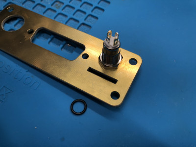
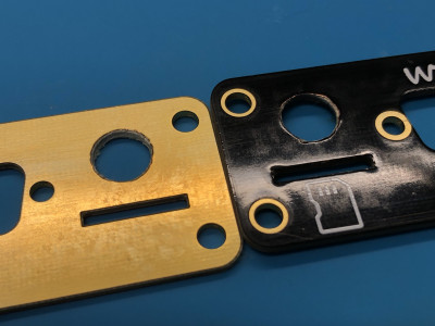
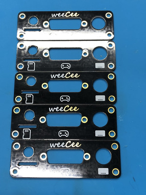
So the update today is mainly around the drilling of the front plate. Overall all of the ones I’ve drilled look good enough - I definitely would highly recommend folk to instead do any cut outs on the PCB itself via forking Rasteri’s work there, even if it means learning a bit of PCB designer, as the results, even when taking into account all the best practices for drilling, are acceptable but not ideal.

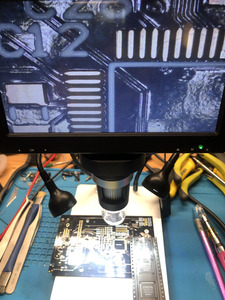
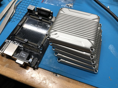
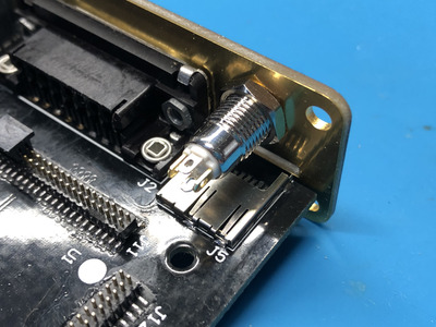
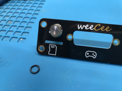
The real saving grace here is that the lip of the drilled hole is going to be covered anyways by the barrel button itself. So the mucky edges aren’t going to be visible in the final product. For sake of viewing, I quickly rigged the plate on to demonstrate both the niceness of it as well as the fact it covers such defects.

Really gotta appreciate all the artists and machinists who do this sort of stuff all the time and can appreciate it when they don’t have to drill holes.

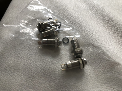
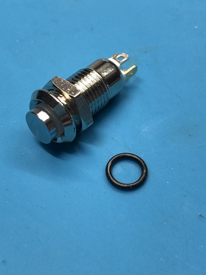
Alas, the testing of the lighting up of the LED inside the button also was fun. Turns out it’s a multidirectional LED where the +/- is reversible, so long as it has the 220 resistor on it. Kinda nice for hooking it up. It’s also a NO (normally open) button which makes it easy to route the - wire to it and then to the RESET pin right next to Battery - pin. So that’s only 3 bodge wires that need ran to it, in addition to the 2 for the battery. Pretty simple setup tbh.

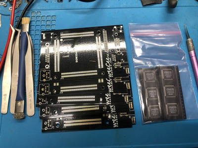
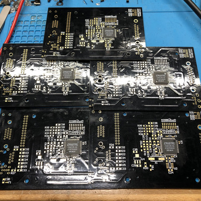
Anyways here’s some pics. Next part is cutting bodge wires to length then soldering them up and putting in some heat shrink piping to make it look clean. Then I will have those that I can solder up and then, at least with the first board, will be able to boot it up and initialize the audio chip. From there just your standard diagnosis to make sure it all works and, debug any issues if any. Here’s hoping that all that handy work worked out.

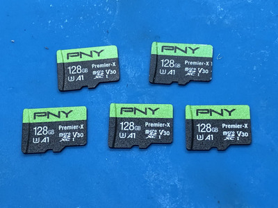
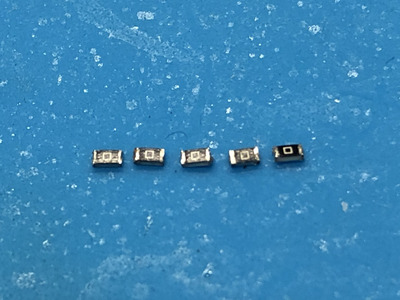
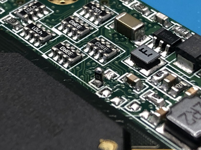
Oh and I still need to tombstone those resistors for the SoMs. I’ll do that next since I have my solder paste out of the fridge.

Attachments

  • 5127568F-3180-46DA-91DA-2B5C11F18D2E.jpeg
    Filename
    5127568F-3180-46DA-91DA-2B5C11F18D2E.jpeg
    File size
    1.99 MiB
    Views
    891 views
    File comment
    Plenty of space to fit the button, even if I may have to do a right angle solder.
    File license
    Public domain
  • 5487BA28-EEEB-4E9B-89D1-F9B639148EC6.jpeg
    Filename
    5487BA28-EEEB-4E9B-89D1-F9B639148EC6.jpeg
    File size
    795.46 KiB
    Views
    892 views
    File comment
    Front side of plate where button covers rough edges via a lip on the button itself.
    File license
    Public domain
  • F8E6C70C-40BE-4AEE-A1EE-65EC02787D1B.jpeg
    Filename
    F8E6C70C-40BE-4AEE-A1EE-65EC02787D1B.jpeg
    File size
    1.89 MiB
    Views
    892 views
    File comment
    Rear side of plate where button covers rough edges via its nut.
    File license
    Public domain
  • D37A4B1D-8172-4811-BD1D-6D681A373101.jpeg
    Filename
    D37A4B1D-8172-4811-BD1D-6D681A373101.jpeg
    File size
    916.75 KiB
    Views
    892 views
    File comment
    Notice the rough edges on the drilled slot. Def want to move this to the PCB design itself to avoid this kind of custom drilling.
    File license
    Public domain
  • 00B7B696-1A7E-4B32-8CD7-7E4836FF5D39.jpeg
    Filename
    00B7B696-1A7E-4B32-8CD7-7E4836FF5D39.jpeg
    File size
    1.99 MiB
    Views
    892 views
    File comment
    Finished drilling front plates
    File license
    Public domain

Reply 438 of 907, by NachtRave

User metadata
Rank Member
Rank
Member

All right there ya go, tombstoned the resistor on the SoM as suggested, that way anyone could just re-enable it if they wanted to.

Pretty delicate work, but worth it. 😀

Attachments