Reply 100 of 175, by stamasd
Rank
l33t
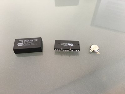
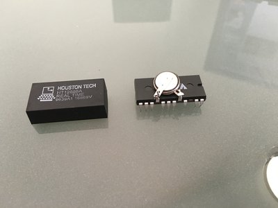
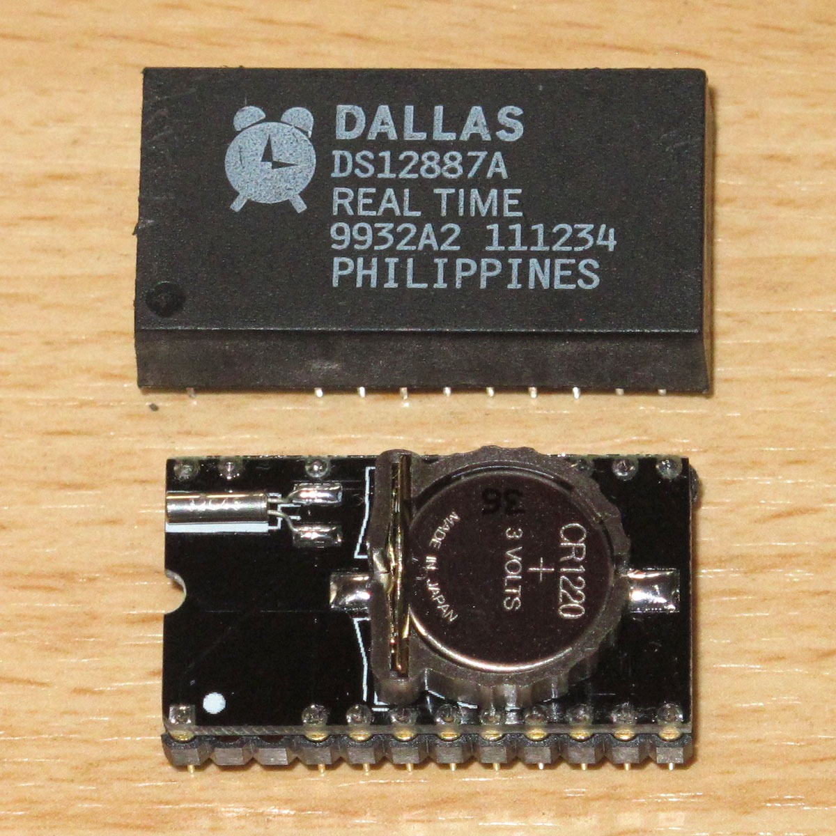
wrote:Is the 12885 compatible with the 1287/ 12887 though? The date code on that chip shows 1995, and I think that is a surface-mount chip and not a through-hole.
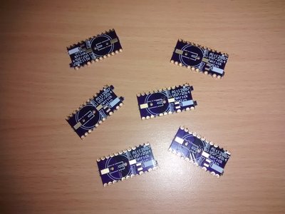
Oh I thought you were referring to components for assembling the board, not the component the boards are meant to replace. You can search Aliexpress for DS12887 too, I remember seeing some at about $3 per piece in lots of 5-10. The one thing about them though is you can't be sure how long they have been in storage and if the embedded battery is any good anymore.
I/O, I/O,
It's off to disk I go,
With a bit and a byte
And a read and a write,
I/O, I/O


