Reply 20 of 48, by cyclone3d

Rank
l33t++
- Rank
- l33t++
Crossing my fingers for you cyclone3d!!!
Well, the two docks I ordered from the same place got canceled because they didn't actually have them.
I did find a PA2731U on eBay for cheap and that one is supposed to arrive tomorrow. At least that is what the tracking says.
I'm not 100% sure if it will fit though as it looks like the laptop it was meant for uses a spacer/adapter to fit the dock that is for my laptop. At least the connection and pinout should be the same.
The PA27312U came today. The connector is correct but, as expected, the laptop will not fit on the dock due to the plastic on the sides of the dock and the metal alignment "hooks" being in the wrong place. I think I am going to take the dock apart and make sure the internals work and then either mod the dock so I can put the laptop on it or build a custom case for the dock internals.
I'll probably mod the dock as it shouldn't be that difficult as long as the actual port is not too low.
Edit - Port is too low because of how the dock case is made. I may be able to make a new top front cover for the dock so I can use most of the dock case as-is.
Update on my 730CDT gameport woes:
- Obtained my PA2724U docking station (designed for Tecra 8000)
- While the 730CDT fits perfectly, none of my joysticks are recognized. The dock does power the laptop, and the external monitor port works, but not the joystick port sadly.
- As you can see, I get a “not supported” blurb on startup whenever dock is connected. it’s starting to look like only very specific models of docking station are comparable (the manuals do specifically indicate comparable models do offer joystick use; I guess I’ll just have to hope a compatible model will be listed on ebay some day (and for reasonable price).
Sorry to report that the PA2724U does not work for my 730CDT, but it does work with my Tecra 8000. I’ve been destroying x-wings with my joystick happily.
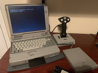
Apologies for adding to this thread after it looks to be resolved, I stumbled on this thread via google searches as i was also looking for a near impossible to get port replicator ( PA2703u) for my recently acquired Toshiba 610CT.
I needed an external vga solution while im in the process of fixing the lcd (waiting for more parts and just in case the lcd is unrepairable).
I was disappointed to see this laptop didnt have a vga port or even an external ps/2 mouse unless you have access to one of the official port replicators.
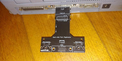
I decided to have a crack at designing an external open mini port replicator using the weird looking 72 pin socket on the back - the pin out i fortunately found in the 610ct service manual ('mini' because im only planning for k/b , video, and mouse - and given the other sockets are already accessible on laptop).
While I couldnt find suitable alternative sockets for this one, Ive gone down the path of designing an accessible and cheaply manufactured pcb (think oshpark, pcbway etc), with appropriate pcb 'fingers' to slot firmly and make contact with each pin in the socket, using spacers to sandwhich a few smaller pcbs together to make it connect safely and then including standard vga etc sockets etc. Hopefully this approach will be successful enough for others to build more low cost open source style port replicators for other models.
Im in the process of making a few last improvements to the schematics/ pcb design before i get a few pcbs made up and can confirm/verify it all works. If all well will then publish it all on github etc and share here (with maybe a few spare pre- assembled if anyone needs one).
As im new to the site, is there a better location to post to for this?
dek
DonkeyBas wrote on 2021-04-24, 23:20:Update on my 730CDT gameport woes:
- While the 730CDT fits perfectly, none of my joysticks are recognized. The dock does power the laptop, and the external monitor port works, but not the joystick port sadly.
While researching pins used on the port replicators for my 610ct, i noticed one pin on the datasheet/ service manual called ' PR check'. I suspect that pin may need to be grounded to tell the laptop a port replicator is connected and activate the other external ports.
Just a hunch, but are there any metal 'holding' clips on your port replicator that could be meant to clip into any metal tabs on the underside of your laptop ?
Thermalwrong wrote on 2021-04-17, 23:51:I was thinking it would be a hassle because the docking connector is something I don't know the part# / name of and the joystick / midi connector pins are on a couple of different rows, so it would need 2 PCBs. I'm thinking you could use the gameport to hold the two together though
I had a similar idea in mind, in effect to re-build the socket using easy to get parts, but with a pin header to bridge the 2x pcbs.
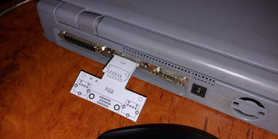
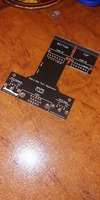
Heres one of the first prototypes (used to get the measurements right), im now waiting on the first batch of pcbs to be delivered so i can test this fully to see that it works.
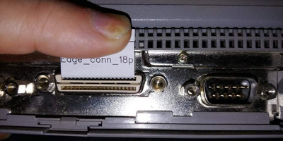
Pins for these sockets look to be spaced approx 1.27mm apart (pitch standard of 1.27)
Each row has top pins and bottom pins - for my toshiba (18pins top/18pin bottom) - should be able to fit a pcb of around 1mm thickness in there.
The space between 1st pcb and 2nd looks to need 2mm - to align to each row.
I used easyeda (free cloud app), and amended/customise an existing 18p edge footprint then started tinkering.
Using the service manual ( contained a 72 pinout in this instance) and verified the ground pins using a multimeter to understand how the pin numbering work)
Then mapped the standard vga, ps/2 sockets to the pins. Assuming the port replicator didnt added any extra resistors or capacitors (fingers crossed)
It hopefully shouldnt be too difficult for anyone to adapt this and make a ~240pins version with all the extra sockets.
Ooh, that's the portege 610CT, I didn't notice this thread got bumped. I was thinking of doing the same thing but keep getting stuck into other projects. That mockup of the adapter looks really good!
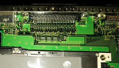
For how it hooks up, I took apart the Libretto 100CT's minidock a while ago and it's got these on its PS/2 port (PJ6):
D23 - apparently a zener diode, probably for surge protection but I'm not sure how that's hooked up
FL9 / FL10 - little inductors for the clk and data lines
R52 / R51 - 10k pull-up resistors that connect to 5v to give a cleaner signal
FL61 - idk, another inductor but bigger and on VCC. I guess for some more filtering
C63 - bypass capacitor for the PS/2 port
------------
Also, for the bigger docks - I'm sorry I told you guys to get those docks, it seems that Toshiba's Tecra range and later satellites (440CDT for instance) do have a whitelist of docks that are allowed to connect. Taking apart a few of them, they've all got little 8 pin serial eeproms in them and I've got the contents of a couple. I've now got the PA2717U (card dock iii) and the basic port replicator for later models (PA2731U) - the connectors are the same but the whitelist stops the PA2731U from working on the Satellite 230CX. I'll need to test out the eeprom contents going from one to the other to see if that allows it to work.
Thats super handy info.
While my initial basic version should hopefully still work, its good to see this - esp if i get weird behaviour on keyboard and mouse due to signal noise or in case it needs pull up resistors to bias the signal to increase compatibility (ive seen strange effects on datalines due to poor wires etc)
If you have taken more pics (even if you have rough schematic scribbles - please upload asevery bit will help)
Can you confirm if the vga socket on that one looks to be just a pass thru or if you can spot any 75 ohm resistors anywhere?
Also does that port replicator have a ' PR check' - if so does it join / connect with the ground plane? (One of my assumptions)
Ill upload my initial schematic here (just need to export it)- so you can get a sense of where currently thinking is ( im keen to get it all exported and onto github - so anyone can review, play and mess around with it).
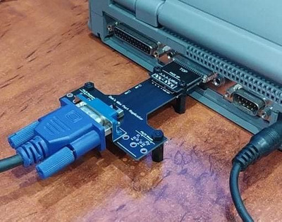
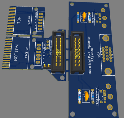
First pcbs arrived, been having issue uploading pics attachments - so hopefully you can see this.
The pcb is 1mm thick - which seems to be a very snug fit (which also limits movement which is good). Still yet to assemble fully, solder, and test all the pin connections further, but initial signs are promising. So fingers crossed i dont fry the laptop.
Thinking i'll add in a idc socket and run a cable between toshiba socket and the ps/2 and vga ports for the final version (will see)
The T shape was to allow enough space to avoid blocking the path of the parallel port and db9 port, useful for the prototype but possibly not for the final.
The end goal is to be able diy building these yourself for under $15.
VGA = tested ok, colors correct, stable image.
..so far so good
VCC = +5.5v
ground correct
doesnt seem to need 'PR Check' connected to anything but will see if its needed for mouse and keyboard.
Created a github and posted the schematic for this here:
https://github.com/dekkit/Mini-Port-Replicato … Keyboard-Mouse-
Will release the pcb gerbers and easyeda repository once ive had a chance to test the ps/2 ports, confirmed they wont release magic smoke, and write up some instructions.
Nicely done, thanks for sharing it!
Regarding the resistors and capacitors for the PS/2 ports, your design should be okay without them. If you do find that it's picky about which devices it will detect, then the CLK and DATA wires would need pullup resistors (10k) connecting them to 5v. You could bodge them on to test whether it helps.
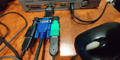
Ok more parts arrived, keyboard and mouse work a treat - but as you can see a very snug fit and a lot of weight.
Keen to add an idc socket and extra cable inbetween to allow more flex and remove stress on the pcb.
Ill add a spot for(optional) pull up resistors, though im happy to report it works fine and responsive without them with my current ps/2 compatible mouse and keyboard from a quick test run.
A few interesting findings:
Was able to verify the behaviour port replicator pin 61 (PRCHEK;000)
- When open and not connected to anything, the vga, keyboard, mouse still work great.
- When this pin is connected to ground, windows 95 detected a new dock, and began installing drivers. Fishing around control panel there was option to configure settings for when docked. An eject button appeared on the start menu too just near shutdown.
While playing around the soundcard settings, i noticed the 610ct hardware supported external midi, i was hopeful that may mean i could add an external midi /joystick socket! However reviewing the 72pin names and seeing more photos of the port replicator suggests it will not be possible.
The official port replicator only has sockets for printer, serial/comm, vga, keyboard, mouse, floppy disk, power in. Further to a previous comment up earlier in the thread, this might be why the joystick didnt work (regardless of the prcheck being grounded)
Thermalwrong wrote on 2022-01-30, 01:57:Regarding the resistors and capacitors for the PS/2 ports, your design should be okay without them. If you do find that it's picky about which devices it will detect, then the CLK and DATA wires would need pullup resistors (10k) connecting them to 5v. You could bodge them on to test whether it helps.
@Thermalwrong
If you could kindly review the next version of the schematic - particularly the placement of the filtering caps - as im working to finalise the next pcb.
https://github.com/dekkit/Mini-Port-Rep ... -01-31.png
Also in the service manual - i ve noticed each pin has number after it (typically 000 or 100 or 110)... Ie for the mouse data line:
"059 MOUSDT;100"
Any idea on what ;100 means or maybe referring to?
I had a look at it and from what I can see, that's how it's set up on the port replicator and should work. Is the bypass cap new too?
Looking at the Toshiba maintenance manual, that notation seems to be common to all of the 90s maintenance manuals. This is just guesswork, but I think it could be the signal type? It seems consistent for grouped types of pins. Generally there seem to be eight types counting in binary? But there are exceptions to that so who knows.
As an example, here's the types of signal that I see on the AMD Interwave's datasheet:
Note:Pin Type: A = analog signal, B = digital bi-directional, C = CMOS compatible, I = digital input, O = digital output, OD = digital opendrain output, P = power or ground, T = TTL compatible, 3S = digital 3-state output
Those can be "B, T" for bi-directional TTL and so on.
There are enough types / combinations there that maybe that's what the 100, 111 etc signifies.
Thermalwrong wrote on 2022-02-01, 23:25:I had a look at it and from what I can see, that's how it's set up on the port replicator and should work. Is the bypass cap new too?
Thank you!
Yes, added 2x bypass caps on the 5v lines for both keyboard and mouse (unless i misread your earlier comment).
As for the other number reference ";100" your explanation sounds reasonable - just odd they didnt explain it anywhere.
On another note, grabbed some additional keyboards and mice to test against v2 once finished.
If you want one of these v1 bare pcb, private message and snail mail one over your way (in case you want to adapt it for other laptops).
Last pcb version design now in production, once tested will upload onto the github and finalise this project.