VOGONS


First post, by appiah4

User metadata
Rank l33t++
Rank
l33t++

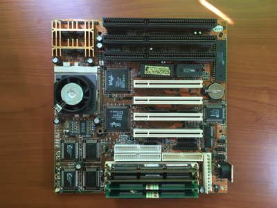
I'm building a 166MMX pc with a PCChips A101 v1.4 mainboard and I'm about to go nuts trying to diagnose a CMOS issue. The boars just refuses to keep settings.

I attached a photo of the board in its current jumper configuration. I cant find a manual for it anywhere but the only jumper settings I can find are here http://www.elhvb.com/mobokive/Archive/PcChips … 01/jumpers.html

Basically there are two jumpers right below the CMOS chip. Jp2 is a 3 header jumper for selecting between 12v and 5v flash rom voltage. This is the red jumper which seems to be in the 12v position. Jp3 is a three header jumper adjacent to it and is apparently the clear cmos jumper. It is the white jumper in photo.

Unless the pin positions are from left to right they are both in 2-3.

As it came the board always booted with cmos battery failure and cmos checksum errors. I assumed a dead battery but replacing the cmos battery did not fix this.

Playing around with the jumpers alone did not fix it either but occasionally lifting the negative contact slightly or pressing down on the right contact or both result in either no cmos battery failed errors (but still checksum error) or a clean boot. The pc can randomly keep bios settings at soft and hard resets from time to time in certain jumper positions but they seem pretty random to me.

I can see no bulging caps.

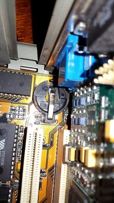
Below is a closeup photo of the battery holder.

What could be wrong? How can I check the holder for a cold or bad solder with a multimeter? I really hope I can fix this...

Attachments

Last edited by appiah4 on 2017-03-18, 21:11. Edited 3 times in total.

Retronautics: A digital gallery of my retro computers, hardware and projects.

Reply 1 of 13, by Jepael

User metadata
Rank Oldbie
Rank
Oldbie

If the battery or holder is not the problem, then maybe the RTC chip is or some component in between them.

Sometimes chips get loose on the socket, so push the VIA VT82885N realtime clock gently downwards and see if it solves the issue.

If that does not help, check the CMOS CLEAR jumper is good because sometimes battery current flows through it so it must not have bad contacts.

Then it's also possible some hero with a screwdriver has accidentally hit a component through which the battery current flows so it is disconnected from the RTC chip.

If you have a multimeter, check if the RTC battery pin has ~3V of voltage.

Reply 2 of 13, by appiah4

User metadata
Rank l33t++
Rank
l33t++

Thanks for the suggestions, but I should note that not only the RTC data (i.e. date and time) but also other BIOS settings get lost when I get the CMOS battery/checksum errors.. So it could be more than just an RTC chip issue (though I will definitely push down on it - I actually did that for the Award BIOS chip before and it did settle down with a slight crack but resolved nothing).

I'm not really sure how to go about checking the rest so a slightly more in depth explanation of how to check the CMOS clear jumper for currents and how to check the RTC battery pin for the voltage would be great. I do have a multimeter, I just don't really know how to use it..

As a side note, I've thought of trying to re-flash the BIOS just in case but I hit a dead end there too. The current BIOS is 03/03/97-i430VX-02071997C-00 with OEM ID Release 03/03/1997S (for Small Block). Browsing online for A101 v1.4 BIOSes does not lead to many hits, but I found these:

https://www.wimsbios.com/biosupdates/pc ... )/2A59GHTB I wish I could download this but it links me to a weird site and I can't find the original BIOS anywhere on it
https://www.wimsbios.com/biosupdates/la ... 0tech)/229 is apparently ajz's large hdd fixed BIOS but unfortunately it can't be flashed onto an A101 board because AWDFLASH complains about wrong part number and when I run the /py switch it complains about chip size not being right.

The BIOS flash chip, I've found by peeling away the Award sticker, is marked H.T. M11704 J9709 which I suppose makes it a Holtek? But I can't find specs on the chip to see if it's 128K as the flash image is.. Not sure if flashing would fix anything but it would be worth a try anyway.

Retronautics: A digital gallery of my retro computers, hardware and projects.

Reply 3 of 13, by Jepael

User metadata
Rank Oldbie
Rank
Oldbie
appiah4 wrote:

Thanks for the suggestions, but I should note that not only the RTC data (i.e. date and time) but also other BIOS settings get lost when I get the CMOS battery/checksum errors.. So it could be more than just an RTC chip issue (though I will definitely push down on it - I actually did that for the Award BIOS chip before and it did settle down with a slight crack but resolved nothing).

It'a all backed up by the same battery, so whatever the issue is, everything will get lost, not just the time.

appiah4 wrote:

I'm not really sure how to go about checking the rest so a slightly more in depth explanation of how to check the CMOS clear jumper for currents and how to check the RTC battery pin for the voltage would be great. I do have a multimeter, I just don't really know how to use it..

Get the RTC chip datasheet, find which pin connects to battery. Use multimeter between this pin and ground. See if changing the CMOS clear jumper changes anything. If there is no voltage, but there is battery, look where the motherboard wires go between the RTC battery pin and the battery - it looks like there is a diode and a resistor and maybe something else too. At some point it should be clear what part is broken if suddenly there is no battery voltage.

Reply 4 of 13, by appiah4

User metadata
Rank l33t++
Rank
l33t++

Right.. I will take a multimeter to the mainboard this weekend and check the following;

1. Measure the voltage of the new battery (just in case it was a new but already old battery) to confirm I get 3V out of it
2. Measure between Pin 20 (VBat) and Pin 1 or Pin 12 (GND) of VIA VT85885N while the PC is unplugged from the wall to see if I get good 3V on the RTC chip. If I get nothing, I'll move the CMOS clear jumper and try again.
3. If I get voltage either way then it's not a problem between the Battery and the RTC chip. If I get nothing on the voltmeter I will trace the route to Pin 20 back to the motherboard, and check each component along the way individually (As far as I can see they are D1 diode, R8 and R13 resistors and the C11 capacitor) to see if they have a 3V, the last one that has no voltage (or the trace leading to it) is the issue?

I'll report back as soon as I try this. What if Voltage is fine at the RTC chip? I want to check the BIOS chip as well but I can't find ANYTHING on it. The text it's labelled with is:

H.T.
M11704
J9709

In the meatime, Should I power the PC on with no jumpers on the CMOS Clear or 12V/5V jumpers and check pins 1 and 3 against pin 2 (Ground I presume) to figure out which is which? I suppoer for 12v/5v I should read 12v on one and 5v on the other. No idea how to interpret what I read on the Clear CMOS jumper though; I assume whatever gives me 3V is the normal operating setting and the other position is clear CMOS?

Also, below is a much clearer photo of how the board was shipped to me (with a P133 Overdrive installed), I only moved the voltage jumper to 2.8V for an MMX CPU.

Attachments

  • aX5N8O.jpg
    Filename
    aX5N8O.jpg
    File size
    1.2 MiB
    Views
    956 views
    File license
    Fair use/fair dealing exception

Retronautics: A digital gallery of my retro computers, hardware and projects.

Reply 6 of 13, by appiah4

User metadata
Rank l33t++
Rank
l33t++
GPA wrote:

you can ignore flash record voltage, it's not flash that is used to save cmos data, it is cmos ram in rtc.

Ooh, so if the RTC has the voltage but fails to retain the info the worst that can happen is I replace it with an identical VIA chip (if I can find one that is..)?

Retronautics: A digital gallery of my retro computers, hardware and projects.

Reply 8 of 13, by appiah4

User metadata
Rank l33t++
Rank
l33t++
GPA wrote:

I think you can imagine a worse outcome, but most probably there is a problem with power delivery, not the chip itself. But I can be wrong of course.

I dare not ask what 😀 I really hope I can get this board to work, I was so happy while building this PC..

Retronautics: A digital gallery of my retro computers, hardware and projects.

Reply 9 of 13, by appiah4

User metadata
Rank l33t++
Rank
l33t++

Findings:

1. When the board is unplugged, there is no voltage to read between Pins 1-2 and 2-3 on JP2 (12V/5V select) which I guess is normal. I have left it at 2-3 position.
2. When the board is unplugged and JP3 is set to 2-3, Pins 1-20 and 12-20 on the VIA chip read 2.8V stable. So far so good. When JP3 is left unclosed, or when JP3 is set to 1-2, Pins 1-20 and 12-20 on the VIA chip read 2.72V.

My amateur conclusion: JP3 is not CMOS reset, and regardless, the RTC chip gets 3V.

I'm guessing time to replace the RTC Chip?

Retronautics: A digital gallery of my retro computers, hardware and projects.

Reply 10 of 13, by Jepael

User metadata
Rank Oldbie
Rank
Oldbie
appiah4 wrote:

My amateur conclusion: JP3 is not CMOS reset, and regardless, the RTC chip gets 3V.

I kind of thought so too based on the jumper being so far from being between battery and RTC chip.

Well, does the RTC retain its settings when only pushing the reset button?
Have you tried if it works better with another power supply?
I ask this because the PSU has "power good" signal which keeps the motherboard in reset until voltages have stabilized close to nominal levels, so it's possible that the "power good" signal does not work properly and the RTC reacts to some glitches on write pulses during powerup/powerdown that then corrupts the data held in memory.

Reply 11 of 13, by appiah4

User metadata
Rank l33t++
Rank
l33t++

No. Ctrl Alt Del and Reset button also cause cmos errors but the battery failed error is less consistent.

I have no other AT PSUs.

HOWEVER I made a big discovery. RTC chip gets 3v when case is laid on its side but when vertical regardless of jp3 setting pin 20 reads 0v against pin 1 or 12! Same deal when upside down. When laid horizontal there is power.

What gives?

Cold solder on battery socket or rtc chip socket? How can I diagnose further?

EDIT: Issue resolved. After determining orientation changed RTC voltage I removed the mainboard from the PC and the battery from the mainboard to find that the old battery had leaked and the (-) connector pin had badly corroded, escaping my visual inspection while in the case. I scraped off the corrosion and wiped it clean, reseated the battery, tested the board vertically and all was well.

Last edited by appiah4 on 2017-03-18, 20:41. Edited 1 time in total.

Retronautics: A digital gallery of my retro computers, hardware and projects.

Reply 12 of 13, by Jepael

User metadata
Rank Oldbie
Rank
Oldbie

Well I did think after seeing the picture that is the battery even of correct size, because it looks like it's too big to fit into the battery holder. Or so it seems, I can't really tell from the picture. Just make sure it is not meant to take smaller battery that goes further into the battery holder and makes better contact.

I'd reseat the RTC and battery, and while the IC socket and battery holder are unpopulated I'd try to clean the contacts with something like isopropanol.

Reply 13 of 13, by appiah4

User metadata
Rank l33t++
Rank
l33t++

The PC is now re-assembled and the CMOS settings stick. Now I need to find a Windows 98SE CD to install onto this thing.. I feel so proud 😀

Retronautics: A digital gallery of my retro computers, hardware and projects.