VOGONS


Reply 960 of 1184, by feipoa

User metadata
Rank l33t++
Rank
l33t++

What's the frequency of that waveform?

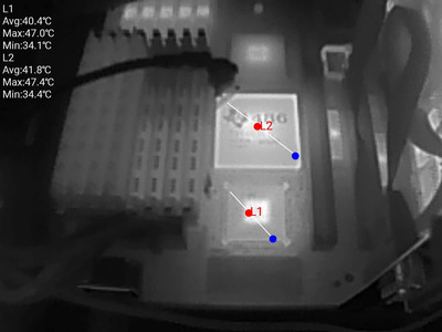
Why did the Vp-p change from mean 285 mV to 128 mV from one scope image to the next? Were you not using low inductance probe in the previous scope images?

Based on what I've seen on my scope's use for its Vp-p auto measurement, it looks looks to be taking the absolute max and absolute min sampled points per sample set, which I believe to be the screen's visible image.

Looks like your scope has more features than mine, which could be a good and a bad thing, depending on what you're after and your skill level.

EDIT: is it just me, or does there seem like there's more going on for your scope image with caps. vs w/out caps?

Plan your life wisely, you'll be dead before you know it.

Reply 961 of 1184, by pshipkov

User metadata
Rank Oldbie
Rank
Oldbie

low induction probe was used only for the measurements in my last post.
thats why the discrepancy in numbers.

in fact i should get better hand of the oscilloscope workflow before posting to avoid confusion, but the feedback here is helpful. shortens the path for me.
thanks.

will follow up with more detailed info.

retro bits and bytes

Reply 962 of 1184, by rasz_pl

User metadata
Rank l33t
Rank
l33t

looks like caps cleaned all the garbage on the second picture leaving only clock harmonics, 40/80/120/160/200 mhz peaks.

Open Source AT&T Globalyst/NCR/FIC 486-GAC-2 proprietary Cache Module reproduction

Reply 963 of 1184, by pshipkov

User metadata
Rank Oldbie
Rank
Oldbie

Rasz_pl,
I expected to see the components of the observed signals in the FFT panel, but in the first measurement the pattern is almost imperceivable (input signal is too noisy and gets decomposed into too many bands ?), while in the second case there are obvious peaks ~40MHz apart that you identified as "clock harmonics".
Can you explain ?

Feipoa,
Frequency is 40MHz. Second image does not show the entire screen - sorry. Same settings are applied to both measurements.

How you achieved that view shown in the first oscilloscope picture (Noise-MIC29302WT.JPG) ?
I am not able to get such view with the device here.

---

Noticing that the oscilloscope does not report the frequency properly every time. Not sure why. Any ideas ?
For example in the first picture it shows 20MHz for some reason, while FSB is clearly 40MHz.
Sometimes that number goes down to something like 50KHz.

I was able to clean-up a lot the waveform on screen by ramping up the level to 4.2V.

retro bits and bytes

Reply 964 of 1184, by rasz_pl

User metadata
Rank l33t
Rank
l33t
pshipkov wrote on 2023-03-28, 07:43:

Rasz_pl,
I expected to see the components of the observed signals in the FFT panel, but in the first measurement the pattern is almost imperceivable (input signal is too noisy and gets decomposed into too many bands ?), while in the second case there are obvious peaks ~40MHz apart that you identified as "clock harmonics".
Can you explain ?

no 😀 I dont do RFI/EMI professionally. Re: Custom interposer module for TI486SXL2-66 PGA168 to PGA132 - HELP!
all I can do is speculate - caps took care of all interference leaving only clock. if you look at levels 40MHz goes down significantly on second picture, from around -30 (cut off the screen so cant see precisely) down to -50.
harmonics https://www.physicsclassroom.com/class/sound/ … y-and-Harmonics
Harmonics might not even be there, might be aliasing inside the scope, might be the way you measure.

pshipkov wrote on 2023-03-28, 07:43:

How you achieved that view shown in the first oscilloscope picture (Noise-MIC29302WT.JPG) ?
I am not able to get such view with the device here.

should be covered in scope manual

pshipkov wrote on 2023-03-28, 07:43:

Noticing that the oscilloscope does not report the frequency properly every time.

because there is no proper frequency to measure, its a power supply line full of interferences

pshipkov wrote on 2023-03-28, 07:43:

I was able to clean-up a lot the waveform on screen by ramping up the level to 4.2V.

how? as in 40MHz signal on top of supply got smaller?

EDIT: Sphere478 feipoa I hate to be this guy, but jlcpcb is currently running a $2 _8 layer_ promo 😀

Open Source AT&T Globalyst/NCR/FIC 486-GAC-2 proprietary Cache Module reproduction

Reply 965 of 1184, by Sphere478

User metadata
Rank l33t++
Rank
l33t++

Okay, so what changes do we want on the release version? Let’s get a wish list. And I’ll see what I can do

Sphere's PCB projects.
-
Sphere’s socket 5/7 cpu collection.
-
SUCCESSFUL K6-2+ to K6-3+ Full Cache Enable Mod
-
Tyan S1564S to S1564D single to dual processor conversion (also s1563 and s1562)

Reply 966 of 1184, by feipoa

User metadata
Rank l33t++
Rank
l33t++

rasz, I have the feeling that JLCPCB may be making that 8-layer promotion permanent. Back in, I think January, they had removed the promotion for a week or so, then it re-emerged and has stayed since. Either the brief removal was a marketing trick, or they received too much backlash from customers to bring it back.

pshipkov, you will probably see different frequencies with the auto function since there are several frequencies occurring all at once. Use the time scale knob to narrow in on the frequencies you wish - if you set the time scale to 100 uS/div, for example, you will narrow in on the 2-5 KHz range, which is the range to make comparison with my noise measurements. I focused on this range primarily because this was the dominate frequency w.r.t. noise. The next dominate was the crystal oscillator's freq. The next dominant was 1/2 the crystal oscillator's freq.

You should use the FFT function at different time scales to show the dominant frequencies. If you aren't seeing anything in the beginning, it is because either 60 Hz is too dominant and you need to adjust the y-scale (voltage) to narrow in on the non 60 Hz amplitudes, or you have set the x-scale to full spectrum, in which case, the 500 KHz and less range is getting smashed into the 60 Hz scale and you won't see them.

You might try using the manual cursors to first pause, then select a waveform and measure it manually as I've shown in some other images in this thread.

Plan your life wisely, you'll be dead before you know it.

Reply 967 of 1184, by feipoa

User metadata
Rank l33t++
Rank
l33t++

Recently, I was fooling around with a QFP IBM 5xc86c on an interposer meant for an IBM Thinkpad. I thought the quantity of decoupling capacitors was rather impressive, since some 486 interposers (the type without VRM's) don't have many, if any, caps. I pulled the caps on another of these interposes I have, which wasn't working, and measured the caps.

They are:

10 pieces of 3.3 nF
10 pieces of 10 nF
7 pieces of 100 nF
4 pieces of 10 uF
------------
31 total

I figured that surely the Vcc noise must be pretty decent, so I selected a point on the PCB's overhang to measure Vcc3, but Vpp with all 31 caps was around 375 mV when run at 2x66 MHz and 3.73 V. The noise was measured in a Lucky Star LS486E revD board, which has an onboard TIP127 voltage regulator. The same interposer, but without the 31 caps, the noise was really bad at 850 mV.

I thought I would share this, considering that the noise we are dealing with on the SXL2 interposer is 90 mV. Makes me t hink that the noise on VCC3 isn't all that important.

Attachments

Plan your life wisely, you'll be dead before you know it.

Reply 968 of 1184, by Sphere478

User metadata
Rank l33t++
Rank
l33t++

Nice! 😀

I got mine mostly assembled a few weeks ago but have been so busy with life to finish.

Also, kinda nervous. To plug it in 🤣. My faith in my soldering skills is a little less than my faith in Feiopa’s soldering skills 🤣

Sphere's PCB projects.
-
Sphere’s socket 5/7 cpu collection.
-
SUCCESSFUL K6-2+ to K6-3+ Full Cache Enable Mod
-
Tyan S1564S to S1564D single to dual processor conversion (also s1563 and s1562)

Reply 969 of 1184, by Sphere478

User metadata
Rank l33t++
Rank
l33t++
image.jpg
Filename
image.jpg
File size
1.72 MiB
Views
1114 views
File license
Public domain

The physical build on my end has been challenging to say the least. My soldering skills areen’t exactly world renowned and there are many fine connections to be made.

I did however after playing with it for weeks/months for a hour here and there far between finally get one assembled that I think was safe to test.

The keen among you will note the lack of a ceramic output cap. I thought I had one in my selection of caps, apparently I was mistaken. I decided to try the unit without it none the less. This may be the reason it isn’t turning on.

The system works before and after the attempt with the built in amd 386 dx 40 but not with the unit installed.

I am getting - - on the post diag card.

Is it possible that the onboard chip isn’t being disabled?

Do we need to add a disable pin for the unit?

I can try again once I have sourced the proper output cap for the unit.

I used a 260? Ohm resistor for the voltage divider and that allowed me to get 3.33v right on the nose with trimming. Unsure if that will allow 5v though. Feiopa, what resistor are you using?

As added precaution I used this handy device for the test. No over current event was triggered.

Thoughts?

Attachments

  • image.jpg
    Filename
    image.jpg
    File size
    1.27 MiB
    Views
    1111 views
    File license
    Public domain

Sphere's PCB projects.
-
Sphere’s socket 5/7 cpu collection.
-
SUCCESSFUL K6-2+ to K6-3+ Full Cache Enable Mod
-
Tyan S1564S to S1564D single to dual processor conversion (also s1563 and s1562)

Reply 970 of 1184, by feipoa

User metadata
Rank l33t++
Rank
l33t++

I see Cout connected. I don't see Cin. If I recall correctly from one of the datasheets, Cin was strongly encouraged.

For MIC regulator, I'm using 121-ohm

For LP regulator, I'm using 1K.

The most likely cause of your non-responsive motherboard with the SXL installed is because you didn't disable the onboard Am386.

Concerning disabling the onboard Am386, you need to either:
a) locate the jumper (or hard-soldered jumper) on the motherboard with disables the onboard Am386, if such a jumper exists, or
b) connect FLT# on the Am386 to GND, e.g. as shown. You needn't lift the lead; you can just solder FLT# to GND assuming FLT# isn't connected elsewhere. If FLT# is connected elsewhere, lift up the pin.

Disable_onboard_Am386DX.JPG
Filename
Disable_onboard_Am386DX.JPG
File size
262.88 KiB
Views
1101 views
File license
CC-BY-4.0

I recall we went over this previously. Did I remember incorrectly?

Last edited by feipoa on 2023-06-18, 09:37. Edited 1 time in total.

Plan your life wisely, you'll be dead before you know it.

Reply 972 of 1184, by Sphere478

User metadata
Rank l33t++
Rank
l33t++

Yeah, I was suspecting bus collisions. From the onboard still being active.

I will have to search for the jumper. I thought that it used a ground pin on the add on socket to short flt on the onboard. But apparently not.

Confirmation pending.

121 ohm sounds like it would probably give me more upper range. This 260? Ohm one os giving me good fine tuning around 3.3v so I will probably stick with it. Thanks for confirming my suspicions that you used something lower ohm for the 5v range.

pshipkov wrote on 2023-05-29, 00:40:

Wouldn't option B cause the CPU to still draw electric power ?
Asking because recently was affected by less than ideal 5V rail issues.
Do you know ?

Putting it in float mode will reduce its power a fair amount. But shutting it down fully will require removal.

Sphere's PCB projects.
-
Sphere’s socket 5/7 cpu collection.
-
SUCCESSFUL K6-2+ to K6-3+ Full Cache Enable Mod
-
Tyan S1564S to S1564D single to dual processor conversion (also s1563 and s1562)

Reply 974 of 1184, by Thermalwrong

User metadata
Rank Oldbie
Rank
Oldbie
pshipkov wrote on 2023-05-29, 00:40:

Wouldn't option B cause the CPU to still draw electric power ?
Asking because recently was affected by less than ideal 5V rail issues.
Do you know ?

I can confirm that it does - I just did this modification for a regular 486DLC CPU and checking it, both CPUs are drawing power and generating heat even though the onboard CPU is definitely inactive.

1685564829037.jpg
Filename
1685564829037.jpg
File size
113.84 KiB
Views
1031 views
File license
CC-BY-4.0

Reply 975 of 1184, by Sphere478

User metadata
Rank l33t++
Rank
l33t++

Yep, it’s awake! But it is just being quiet on the bus. that is what allows the other one to work. Something similar to this is how dual Pentium ones work.

Sphere's PCB projects.
-
Sphere’s socket 5/7 cpu collection.
-
SUCCESSFUL K6-2+ to K6-3+ Full Cache Enable Mod
-
Tyan S1564S to S1564D single to dual processor conversion (also s1563 and s1562)

Reply 976 of 1184, by feipoa

User metadata
Rank l33t++
Rank
l33t++

If either of you plan on desoldering the Am386DX, could you measure the 5V rail at the PGA CPU before and after removal of the Am386DX? I'm wondering how much voltage drop, if any, exists while having the Am386DX remaining installed and inactive. If you have a scope, it would also be interesting to see if the noise level changes, and if so, how much.

Plan your life wisely, you'll be dead before you know it.

Reply 977 of 1184, by Sphere478

User metadata
Rank l33t++
Rank
l33t++

I’m kinda taking my time on this, I don’t want to remove the cpu. I think it is cool that it is there.

I do want to study how a normal 386 pga chip disables it though. We may be able to add that to the interposer.

A quick look at my motherboard didn’t show any jumpers for disabling the chip but I have to think there is a jumper or the pga cpu disables it somehow.

I thought it left a ground floating on the board that the pga cpu jumped but apparently not, or we missed adding it on the pinout.

So long story short, I want to look into this deeper before I mess with the pins.

Surely there is a jumper, or a way the new cpu disables the onboard cpu. They surely can’t have expected the end-user to move a pin like that, in order to upgrade the cpu?

Sphere's PCB projects.
-
Sphere’s socket 5/7 cpu collection.
-
SUCCESSFUL K6-2+ to K6-3+ Full Cache Enable Mod
-
Tyan S1564S to S1564D single to dual processor conversion (also s1563 and s1562)

Reply 978 of 1184, by Sphere478

User metadata
Rank l33t++
Rank
l33t++

Okay I finally got the 10uf capacitors in, I went ahead and installed them on all the 5v pads. Why not…. Verified 3.33v at interposer and installed sxl2

Anyway. Still no post codes.

The board boots off the onboard dx-40 with the interposer installed but not with interposer and sxl2 installed.

I don’t have any 386 cpus to try in this motherboard. I was supposed to get a bunch from someone but they never sent them. 🙁

That kinda messes up my plans, I’m a little short on money rn so probably won’t order one.

I was going to take the multi meter and study the grounds on a pga 386 and do some tracing on the motherboard to try and figure out how a normal 386 disables the onboard 386 but I don’t have the cpu.

Trying to find the datasheet for that amd dx-40 … anyone spotting that online somewhere?

Next time I get a second I am going to try and trace the flt pin from the cpu as indicated and see where the traces take it.

I did try jumping the indicated pins in previous post it led to over current event on my at2atx adapter. Best guess is that pin is being pulled high by the motherboard. And that created a 5v short. I didn’t pull the pin as I recall it being said that it was okay to jump it without pulling it up this seems to not be the case. Board is fine though. 😀 thanks to that device. I still don’t see a jumper for doing this?

If it really comes down to it I can pull the cpu, but I kinda really want to leave it there unmolested.

Attachments

  • image.jpg
    Filename
    image.jpg
    File size
    1.56 MiB
    Views
    895 views
    File license
    Public domain

Sphere's PCB projects.
-
Sphere’s socket 5/7 cpu collection.
-
SUCCESSFUL K6-2+ to K6-3+ Full Cache Enable Mod
-
Tyan S1564S to S1564D single to dual processor conversion (also s1563 and s1562)

Reply 979 of 1184, by feipoa

User metadata
Rank l33t++
Rank
l33t++

If you have already connect FLT# to GND and it caused an over current condition, then try lifting up the pin as I've shown in my photo and bend it to the side (GND). Thinking about this further, I think you can only wire FLT# to GND if the motherboard isn't connecting it to Vcc. FLT# has an internal pull-up resistor and, according to the datasheet, if FLT# is not used, it should be left disconnected. Thus I am surprised that your motherboard was sending FLT# to Vcc. However, if you look at the photo I provided, it looks like FLT# on my motherboard was also being sent to Vcc, in contravention to the datasheet. It has been many years since I did this mod, but it looks like I did the pin left up because I noticed FLT# was going to Vcc. Sorry, I didn't remember this.

You really need to get any PGA132 CPU to continue testing, preferably a Cx486DLC or Tx486DLC. These should be like $15 max. EDIT: I just looked on eBay, and am in disbelief, wow! There's tonnes of these chips, but how did the price of jump to $50 or more? Cheapest I could find was $40 https://www.ebay.com/itm/134349014775 I suggest hit up CPUShack to see if he has any extra he doesn't need. He probably does because I cannot see these selling on CPU-World since collectors already have them.

The datasheet for the A80386DX can be found on digikey. They are still selling these!
https://www.digikey.com/en/products/detail/ro … DXL-25/12095484

By the way, you should be running your SXL2 at 3.6 V or higher, not 3.3 V.

Plan your life wisely, you'll be dead before you know it.