VOGONS


First post, by Anaxagoras

User metadata
Rank Newbie
Rank
Newbie

Hi.

I am restoring and tunning my 486.
At the moment, there are two things that I could not repair.

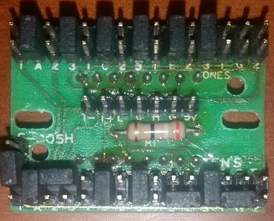
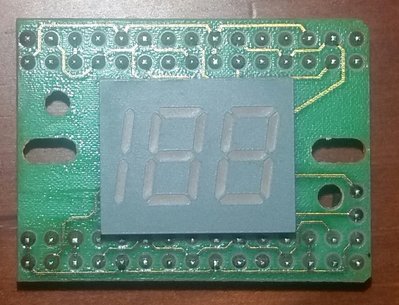
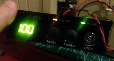
One of them is the display located in the front panel case, the CPU Clock Speed Diplay.

20171001_010449.jpg
Filename
20171001_010449.jpg
File size
1.11 MiB
Views
1050 views
File comment
Front panel
File license
Fair use/fair dealing exception

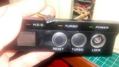
The CPU is an Intel 486 DX4/100Mhz. 66 Mhz in "normal" mode and 100 Mhz in "turbo" mode.
In the mainboard side I found the place to connect the Turbo switch and Turbo LED, both works. The LED turns ON when the Turbo button is pressed.

20171001_004620.jpg
Filename
20171001_004620.jpg
File size
249.97 KiB
Views
1050 views
File comment
Display gaps
File license
Fair use/fair dealing exception
20171001_004918.jpg
Filename
20171001_004918.jpg
File size
180.55 KiB
Views
1050 views
File comment
Display
File license
Fair use/fair dealing exception

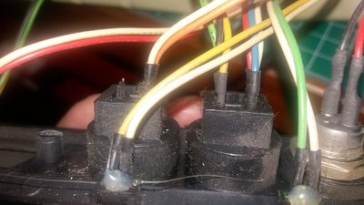
From the Turbo button there are other cable that I suppose was connected to the numbers display.

20171001_010550.jpg
Filename
20171001_010550.jpg
File size
1.38 MiB
Views
1050 views
File comment
Turbo button
File license
Fair use/fair dealing exception

And here is the problem, the numbers display is allways off.
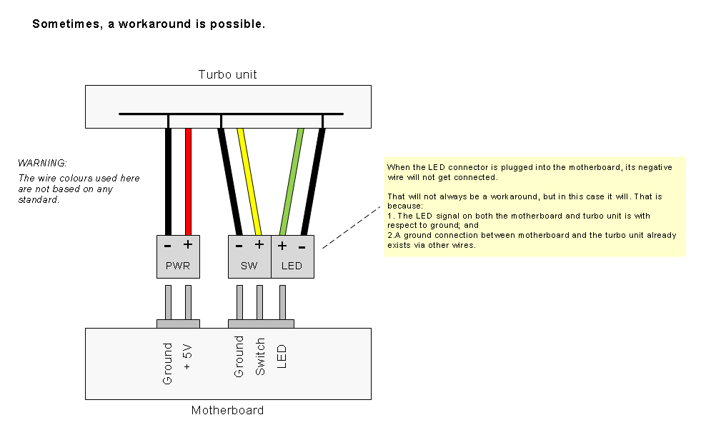
I had try to connect the cable in all free positions using the three gaps but nothing seems works.

How can I solve this problem?
Can I find a replacement with easy?

Thanks a lot!

My computers

qp92nk-6.png

Reply 2 of 5, by TheMobRules

User metadata
Rank Oldbie
Rank
Oldbie

For the numbers display to work you need to provide +5V from the power supply. It's the last two pins in the center row of the display, labeled G (Ground) and 5V.

Most AT power supplies came with a 2-pin +5V connector for this purpose, if yours does not have it you can build one, or use one of those Molex to 44-pin IDE power adapters.

Reply 3 of 5, by zakurowrath

User metadata
Rank Newbie
Rank
Newbie
TheMobRules wrote:

For the numbers display to work you need to provide +5V from the power supply. It's the last two pins in the center row of the display, labeled G (Ground) and 5V.

Most AT power supplies came with a 2-pin +5V connector for this purpose, if yours does not have it you can build one, or use one of those Molex to 44-pin IDE power adapters.

I actually have the same problem and can't find a jumper to molex adapter anywhere, glad you suggested the Molex to 44 Pin IDE adapter TheMobRules, wish someone still sold them like the one in the picture below. Ask for building your own, I found the "Dupont Jumper" header, just curious what the wire gauge should be?

osiW0V.png

Reply 5 of 5, by Anaxagoras

User metadata
Rank Newbie
Rank
Newbie

Yeah!

20171007_215135.jpg
Filename
20171007_215135.jpg
File size
1 MiB
Views
938 views
File comment
100Mhz :)
File license
Fair use/fair dealing exception

Thank you very much.
All answers have helped me.

I made a cable to take the power from the CPU fan connector to the two first pins (+5V and G) in the display.
With this, the number 50 is displayed. 😀

After this I closed the next two pins with a jumper, only for testing, and then the number changes to 100 😁
Since I have no key to lock/unlock the keyboard I decided to use their cable from turbo button to display's pins 3 and 4.

After all is similar to turbo_switching schema provided by SSTV2.

Thanks to all again.
😊 😊 😊 😊

My computers

qp92nk-6.png