VOGONS


Toshiba T5200 mods and upgrades

Topic actions

Reply 360 of 539, by djrm

User metadata
Rank Newbie
Rank
Newbie

Hi everyone, My name is David and I'm a new member here. I found the group whilst searching for inforation on the T3200SX which I have just aquired. I have a few vintage computers and some modern simuulations of other old machinees.

There sure is a lot of interesting reading here. I'm about to upgrade the bios in readiness for fitting a flash hard disk and an externl gotek. Yesterday I got it working with an old ISA network card to telnet itto a local server. I think the other slot would be an ideal place to put my old 1200 bps modem.

The photo shows the parallel port to floppy-gotek adapter ive just wired up.
Kind regards, David.

20200702_134505-COLLAGE.jpg
Filename
20200702_134505-COLLAGE.jpg
File size
156.91 KiB
Views
1760 views
File license
Fair use/fair dealing exception

Reply 361 of 539, by shimart

User metadata
Rank Newbie
Rank
Newbie
djrm wrote on 2020-07-02, 12:50:
Hi everyone, My name is David and I'm a new member here. I found the group whilst searching for inforation on the T3200SX which […]
Show full quote

Hi everyone, My name is David and I'm a new member here. I found the group whilst searching for inforation on the T3200SX which I have just aquired. I have a few vintage computers and some modern simuulations of other old machinees.

There sure is a lot of interesting reading here. I'm about to upgrade the bios in readiness for fitting a flash hard disk and an externl gotek. Yesterday I got it working with an old ISA network card to telnet itto a local server. I think the other slot would be an ideal place to put my old 1200 bps modem.

The photo shows the parallel port to floppy-gotek adapter ive just wired up.
Kind regards, David.
20200702_134505-COLLAGE.jpg

I also have a t3200sx. I have successfully upgraded RAM using the information here.
Also, I want to connect Gotek as an external drive.
I want to know if you have successfully upgraded your BIOS and connected Gotek.
If you've been successful, I look forward to sharing your great ideas with everyone.

Reply 362 of 539, by 16ShadesOfOrange

User metadata
Rank Newbie
Rank
Newbie

@djrm- welcome! Your adapter is a cool idea, especially putting on a board like that.

While I've made some progress with my rig, it hasn't been smooth sailing.

The good:

  • I threw in an ISA sound card, and used UNISOUND (from a fellow vogon'er) to get it working easily
  • I ripped a small PC speaker out of a desktop PC and mounted it under the keyboard, and connected it to the sound card. I did try the built-in speaker but it was too quiet, this new one is pretty good! 🔊
  • My chinese "silent" fans arrived and are installed

The bad:

  • The "silent" fans sound terrible 📢and are barely quieter than the factory ones (guess I cheaped out)
  • In an attempt to quieten the fans and give them 6V instead of the 12V from the PSU connector, I shorted out 2x 12V PSU fan connectors 😱(they're dead) so I'm now running 3x 12V fans in parallel from the single left-side fan connector. I opened up the PSU but can't see any obvious issues, so for now it's running
  • I busted my screen somehow 😥. Seems to work OK in graphics mode eg full screen stuff like in Windows, but in DOS mode it's almost inverse, eg black is orange, the display sometimes becomes distorted/picks up interference, text becomes wobbly and almost unreadable.

    This is how it should look:
    _zjbcpdj1ICWi1T_cYC9s4vJhoB0FwqprmvA5b3d1UCTb4Nthi9R17tphpjQhRPU45dc3G8GHk-iidNTdAj_i_B3z3c0jPzIfJukgIOsQl46rz3CSb4zdTkkJDbjvwapK6ctJEM81e63n8u-2fsu2Raj7e3qu60leKTJyMxKxaBifS9-kz-FYxFkmwpjYmhR7UMLst8RIIOOStvM_O6INchN-qYhxZ2VApNBggAFL-GO6PUIkGXRZyhqvG1aOGwq8FEZiZfuKoMcUkT9dr_FpnHGOwUAdUHuZvkbdJbmxSaHh0gHhMFBG5nmAJy3Xd5tOR40Dr7sWGV2NBiRBCtplk7xPrfPT4_YI07w00aj-HvG7OLFRkXzUy3MZnA8YpH1Bek8pV_0_EfDBhhrR0QVLUBBxKY26RbpxFDv9XUTyq9BJnUlBqNS5-tFL8D9bezetBGUH5Zbm8OapeB0I4WFtgQQo60DybT8f6_GqvWy7ILMADKYz0Mvc84MQss0yFJhBFcjH8Ov0ZMNzUQ2ZuhkJZ46EXPCoMVpG7BlB9tY_eea8UsW6U0UceTu2k5xmh0UcahFkMGxOeNpFIPMg8k8Ct2Tuw1IewHFqKarovT3fCKx7KQE8EANKBtVFaGdj7BQQ0n9qOInj2Amy4kUc9OlfRU75sof6mA656x7lYp9e0TUVU8RZsZ3HkzO33wD6xlFKWdLFAq9JBvbzLUItsfOU0WZXdnXz-yAykgAqpv5ALvwBCYJZXtWRWA=w440-h331-no?authuser=0

    This is how it looks now:
    TZ7XnZruWPrISMaLIMocoE9LrHHoqJ14KOS-qvXg6j17YVOYZ18N0vvn0zuao0wSxC8BYgUfNTdGLtgR1IM7kG8Veq_BS4ANkoxG0cu3jS4hEeSojYhZ8-1nfWt53ZUxrnbpzcU3aeJ2mVOXi9VVcasDWKRSy4OggvhO5jKB93VtkOd-8vOPijKUsTgT9cl4ainauq0z4aEHpsiogkIGddwQBGUxNhKv2TUec90vO4oXJrO2zHEAk4tTPGfV7DEKRiJWX47OVdya0b6SMM7q0czJUWWXjVsL3cC8yfe9fLMuucHM-XhKlfUMo1aoF97yyPt0kjkMDF-D3pV_W60hi2BPLp8VNvxdmt-aRGZ6w0v-H-MvQpYW5Q_FzAqaQDBsSuBc_ZFmfeBOV7FDh5j0Y6lHzA9L0uHTpRbgZBKflxQBnxnQ2L99_c7Fh2dEgG_TprqmAQl8lnnAWkVcwdOQwGDRywjyXfIRxzXSoEi2p_pes47GsyGmROGQ5zPWHiKw50EDSQFF6WIo9FNQP4GJ7qpttPZiOUa0E9wAi2tu7sCMh488-r6CmaBJoT62OFbt26zDd5j_4uqRv64Ow9qZI_b5cYksXNtsA6o3hjz3V8mLgmhhV6IsfxS_6U56_wMMbPVVs-H4tAZ7DBlNO6ELhQdVDsNy3gkak-owXVjuG7sFtqcN9B73XhEHRV_PvtQuFjy9mCJbGxbDXcU5qoKMdIsyIGesAP4_sB7rOUOfIQf8RX0lkr8v3ug=w445-h333-no?authuser=0

    If anyone has any ideas or has seen this before, please let me know 🤞. I've tried re-seating all the screen connectors etc. Have also reset CMOS and fiddled round in there. Worth noting that it doesn't affect the external output at all. Cheers guys!

💻 Toshiba T5200 info
💻 Toshiba T3200SX info
💻 Toshiba T3200 info

Reply 363 of 539, by konrad_pentium

User metadata
Rank Newbie
Rank
Newbie

Firstly, a HUGE THANK YOU to the eBay seller who turned me onto this site, IanB and the admin(s) at VOGONS!

I have two T5200s (one monochrome, one color) that I used until the late 1990s because they were a "portable" with an ISA slot. After sitting for 20 years, I did not have a single HDD or FDD that worked properly.

After finding a slow enough computer to run my old device programmer, I burned Ian's patched BIOS. Wow, the ancient Toshiba instantly booted from Compact Flash! I am totally impressed. I also fabricated internal and external floppy cables. Ian, your documentation is concise, easy to follow, and greatly appreciated.

I'll post two photos that may help others. I found the cable fabrication a challenge, but my eyesight is not what it used to be. I held the IDC connector in a block used to press connectors together and tapped on the top with a small hammer to seat individual wires. Heat shrink covers one wiring error.

IDC Technique.JPG
Filename
IDC Technique.JPG
File size
207.72 KiB
Views
1666 views
File comment
IDC Technique
File license
Public domain

For the external floppy cable, I used heat shrink to provide some extra mechanical support (as well as insulation) for the delicate wires. During assembly, I "dotted" all the ground wires with a fine-tip Sharpie to make things easier to follow. I also plugged the IDC header into a FDD and the DB-25 into an RS-232 breakout box so I could easily probe the wiring for proper connectivity. Next time, I would not tin all the ground wires as that made a 3-conductor bundle difficult to insert into the solder cup. A small thermal wire-stripper (HOTweezers) made quick work of removing insulation. I also used a 1N5819 as that's what I keep on hand.

Printer Port Floppy Connector.JPG
Filename
Printer Port Floppy Connector.JPG
File size
202.05 KiB
Views
1666 views
File comment
Printer Port Floppy Connector
File license
Public domain

Finally, as a new member here I'm not yet permitted to send personal messages. So if the eBay seller would please contact me, I'd appreciate it.

Last edited by konrad_pentium on 2020-11-14, 23:22. Edited 1 time in total.

Reply 364 of 539, by my03

User metadata
Rank Member
Rank
Member

Very nicely done konrad_pentium 😀 I assume that your original FD did not work? What did you replace it with?

I did replace my own floppy some time ago (also had to replace the Connor HD that was completely dead. Settled for a DOM-module). What bios did you settle with in the end (Phoenix or Award)?

Reply 365 of 539, by konrad_pentium

User metadata
Rank Newbie
Rank
Newbie

Thank you my03. I actually have thee non-functional original floppy drives. Some electrolytic capacitors in all three had clearly leaked. I replaced those caps and left the ones that exhibited good ESR. Unfortunately, this did not restore any FDD to working condition. It's difficult to say if all their PCB traces are intact, as I have no schematic. I probably will investigate further, but at least now have a workaround. So far, I've made no permanent replacement of the floppy.

Initially, I made a clone of my original BIOS just to prove I could. I noticed it said Phoenix, so that's the only thing I've tried.

Reply 366 of 539, by konrad_pentium

User metadata
Rank Newbie
Rank
Newbie
konrad_pentium wrote on 2020-11-14, 23:21:

I actually have thee non-functional original floppy drives. Some electrolytic capacitors in all three had clearly leaked. I replaced those caps and left the ones that exhibited good ESR. Unfortunately, this did not restore any FDD to working condition.

Just wanted to amend this. Turns out I was trying to test the internal floppy with the A-B-PRT switch in the A position. I actually had fixed two of the FDDs by replacing capacitors (and 1 zero-ohm jumper). The third still won't spin. In my case, it was readily apparent which capacitors were bad as they had leaked and corroded the PCB.

Repairing this type of damage can be challenging. It's difficult to get the PCB clean enough without pulling up the SMT solder pads. I used repeated application of Kester 186 liquid flux, desoldering braid, solder, and a commercial flux remover (although acetone works as well).

Bad Capacitors.JPG
Filename
Bad Capacitors.JPG
File size
267.77 KiB
Views
1636 views
File license
CC-BY-4.0
Bad Capacitors Fixed.JPG
Filename
Bad Capacitors Fixed.JPG
File size
237.38 KiB
Views
1636 views
File license
CC-BY-4.0
Another style.JPG
Filename
Another style.JPG
File size
206.78 KiB
Views
1636 views
File license
CC-BY-4.0

I also fabricated an extension cable so I could work with the floppies while they were outside the machine. Repeated installation/removal for testing was something I wanted to avoid. I did not have any 26-pin male connectors, but larger ones will work as the locating key keeps the mating connector centered. It's a simple matter to extract excess pins.

FDD Extension Cable.JPG
Filename
FDD Extension Cable.JPG
File size
191.91 KiB
Views
1636 views
File license
CC-BY-4.0

Reply 367 of 539, by shimart

User metadata
Rank Newbie
Rank
Newbie
IanB wrote on 2018-01-31, 22:41:
Here are details for the external floppy drive mod. Use this info at your own risk, don't blame me if you damage your T5200! Not […]
Show full quote

Here are details for the external floppy drive mod. Use this info at your own risk, don't blame me if you damage your T5200!
Note that although general file access appears to work on a standard T5200, the OS will think the drive is a 1.2MB 5.25" floppy so booting and formatting won't work.
If you update your BIOS with any of the versions I posted earlier in this thread then these problems are fixed and the OS will recognise the drive as 1.44MB 3.5"

First fit a 34 way IDC header on to one end of a 34 way ribbon cable and then wire up the other end to a 25 way 'D' connector as follows:

wire 2 to pin 14 (Density select)
wire 4 not connected
wire 6 not connected
wire 8 to pin 2 (Index)
wire 10 not connected
wire 12 to pin 10 (Drive select)
wire 14 not connected
wire 16 to pin 11 (Motor on)
wire 18 to pin 16 (Direction)
wire 20 to pin 17 (Step)
wire 22 to pin 12 (Write data)
wire 24 to pin 13 (Write enable)
wire 26 to pin 3 (Track 0)
wire 28 to pin 4 (Write protect)
wire 30 to pin 5 (Read data)
wire 32 to pin 15 (Side select)
wire 34 to pin 6 (Disk changed)

wires 1,3 to pin 20 (Ground)
wires 5,7,9 to pin 21 (Ground)
wires 11,13,15 to pin 22 (Ground)
wires 17,19,21 to pin 23 (Ground)
wires 23,25,27 to pin 24 (Ground)
wires 29,31,33 to pin 25 (Ground)

Connect a 1N5818 schottky diode between pin 1 (ready) and pin 11 (Motor on) with the banded end towards pin 11

Cable + Gotek Floppy emulator:
FloppyCable1.jpg
'D' Type connector pins 1-13
FloppyCable2.jpg
'D' Type connector pins 14-25
FloppyCable3.jpg

Closeup of modified Gotek emulator with flash floppy firmware, Oled display and rotary encoder mods
FloppyCable4.jpg

To use: Plug the cable into the printer port and set the control switch on the left hand side of the keyboard to the "A" or "B" position depending on whether you want the external drive to be "A" or "B" (You can boot from it when set to "A")
Set the switch back to PRT to use the printer port as normal.

Thanks very much to lanb.
I also made my own cable to connect the external drive.
Equipped with Gotek, it works very well.
I'm using a T3200sx, so it's the default BIOS.
It recognizes it as a 1.2mb drive.
I'd also like to burn a bios that recognizes a 1.44mb external drive.

Attachments

Reply 368 of 539, by konrad_pentium

User metadata
Rank Newbie
Rank
Newbie
my03 wrote on 2020-11-14, 21:26:

What bios did you settle with in the end (Phoenix or Award)?

Since I have two machines, I burned the Award BIOS for the second (especially since that's what was in it). Both are the himem versions. Can't say I can tell any difference in operation between the two. The Award BIOS seems to count up memory faster at boot-up, and its CMOS setup screen is more to my liking -- so I guess that's the one I prefer.

Unrelated, but wanted to comment that 16ShadesOfOrange is a brilliant username (wish I had been creative enough to have come up with that). I enjoyed your T5200 disassembly/parts pics too!

Reply 369 of 539, by konrad_pentium

User metadata
Rank Newbie
Rank
Newbie

There's a lot of discussion here regarding the T5200's CMOS battery. I'll add a few measurements/comments:

If you connect a voltmeter in place of the battery with the machine running, you can measure the battery charging voltage. It's not constant. I've seen it start out as low as ~0.2V and ramp up to ~1.4V after an hour. Another time it started at ~0.7V (but this was possibly my other T5200 and there may be variations in individual machine circuit performance).

If you measure current flowing into the battery port with the machine switched off, you can see how much the CMOS consumes at various battery voltages. I measured this (by substituting a bench power supply for the battery) from 3.9V down to 0.7V in 0.1V steps. It follows a fairly predictable curve, so I'll only list a few points:

3.9V is 76 uA (micro-amperes)
3.0V is 34 uA
2.5V is 18 uA
2.0V is 7 uA
1.5V is 2.5 uA
1.0V is 1.4 uA
0.7V is 0.9 uA

At 0.7V the setup memory was still intact, but I doubt it would be below about half a volt. This is very good performance. Low-power CMOS SRAM of that period was only guaranteed down to about 2 volts. Ambient temperature and the performance of the particular IC affects this.

As for my own CMOS battery, I employed some well-used 3.7V AAA lithium packs from portable phones. They were no longer suitable for that applications, exhibiting a voltage of only 2 to 2.5 volts after charging and sitting idle.

There was, as expected, zero current flowing into the battery while the laptop was running. This is due to the battery voltage (2 to 2.5V) being greater than the charging voltage (less than 1.5V).

Reply 370 of 539, by shimart

User metadata
Rank Newbie
Rank
Newbie
shimart wrote on 2020-11-24, 10:05:
Thanks very much to lanb. I also made my own cable to connect the external drive. Equipped with Gotek, it works very well. I'm u […]
Show full quote
IanB wrote on 2018-01-31, 22:41:
Here are details for the external floppy drive mod. Use this info at your own risk, don't blame me if you damage your T5200! Not […]
Show full quote

Here are details for the external floppy drive mod. Use this info at your own risk, don't blame me if you damage your T5200!
Note that although general file access appears to work on a standard T5200, the OS will think the drive is a 1.2MB 5.25" floppy so booting and formatting won't work.
If you update your BIOS with any of the versions I posted earlier in this thread then these problems are fixed and the OS will recognise the drive as 1.44MB 3.5"

First fit a 34 way IDC header on to one end of a 34 way ribbon cable and then wire up the other end to a 25 way 'D' connector as follows:

wire 2 to pin 14 (Density select)
wire 4 not connected
wire 6 not connected
wire 8 to pin 2 (Index)
wire 10 not connected
wire 12 to pin 10 (Drive select)
wire 14 not connected
wire 16 to pin 11 (Motor on)
wire 18 to pin 16 (Direction)
wire 20 to pin 17 (Step)
wire 22 to pin 12 (Write data)
wire 24 to pin 13 (Write enable)
wire 26 to pin 3 (Track 0)
wire 28 to pin 4 (Write protect)
wire 30 to pin 5 (Read data)
wire 32 to pin 15 (Side select)
wire 34 to pin 6 (Disk changed)

wires 1,3 to pin 20 (Ground)
wires 5,7,9 to pin 21 (Ground)
wires 11,13,15 to pin 22 (Ground)
wires 17,19,21 to pin 23 (Ground)
wires 23,25,27 to pin 24 (Ground)
wires 29,31,33 to pin 25 (Ground)

Connect a 1N5818 schottky diode between pin 1 (ready) and pin 11 (Motor on) with the banded end towards pin 11

Cable + Gotek Floppy emulator:
FloppyCable1.jpg
'D' Type connector pins 1-13
FloppyCable2.jpg
'D' Type connector pins 14-25
FloppyCable3.jpg

Closeup of modified Gotek emulator with flash floppy firmware, Oled display and rotary encoder mods
FloppyCable4.jpg

To use: Plug the cable into the printer port and set the control switch on the left hand side of the keyboard to the "A" or "B" position depending on whether you want the external drive to be "A" or "B" (You can boot from it when set to "A")
Set the switch back to PRT to use the printer port as normal.

Thanks very much to lanb.
I also made my own cable to connect the external drive.
Equipped with Gotek, it works very well.
I'm using a T3200sx, so it's the default BIOS.
It recognizes it as a 1.2mb drive.
I'd also like to burn a bios that recognizes a 1.44mb external drive.

I burned the rom. by TL866ii (I got it from Ali Express a few days ago.)

<T3200SX BIOS V1.10 + new VGA (Award) patch 1.0 with LOMEM XTIDE 640K>

It Works very Well.
External Gotek recognizes it as a 1.44mb drive! 😀
The XTIDE bonus made me happy.
As a Second bonus, it may be just my feelings, but it seems that the frequency of the plasma display monitor is stable.

However, I am having a problem with the <Serial Mouse> not working on the My T3200sx.
If someone knows how to fix it, please give me some advice.
Even if I run TEST3.COM and try to adjust the SERIAL COM PORT in the BIOS, the <Serial Mouse> is not recognized.
I would really appreciate it if someone could advise me on this matter.

Attachments

Reply 371 of 539, by adalbert

User metadata
Rank Oldbie
Rank
Oldbie
shimart wrote on 2020-12-05, 15:39:

However, I am having a problem with the <Serial Mouse> not working on the My T3200sx.
If someone knows how to fix it, please give me some advice.

I have T3200SXC and I found out that not every mouse works with it. What is the model you are trying to use? 3-button Logitech Mouse Man worked out of the box, but I had problems with other devices. I had to re-wire connectors in order to make them work. I modded A4Tech mouse by disconnecting pin 5 (GND) in DB9 connector and connecting it to pin 6 (DSR). I also bridged pin 4 (DTR) with pin 6.

Here are some details about getting mouse to work: Re: Connector wiring NCE-860/PC mouse (late 80s serial port)

BTW I dumped T3200SXC BIOS while ago if anyone needs it: Re: 80386 BIOS image collection
and here are schematics for replacement PSU DIY AT DC-DC power supply (replacement for Toshiba T3200SXC and others)

Repair/electronic stuff videos: https://www.youtube.com/c/adalbertfix
ISA Wi-fi + USB in T3200SXC: https://www.youtube.com/watch?v=WX30t3lYezs
GUI programming for Windows 3.11 (the easy way): https://www.youtube.com/watch?v=d6L272OApVg

Reply 372 of 539, by shimart

User metadata
Rank Newbie
Rank
Newbie
adalbert wrote on 2020-12-05, 16:06:
I have T3200SXC and I found out that not every mouse works with it. What is the model you are trying to use? 3-button Logitech M […]
Show full quote
shimart wrote on 2020-12-05, 15:39:

However, I am having a problem with the <Serial Mouse> not working on the My T3200sx.
If someone knows how to fix it, please give me some advice.

I have T3200SXC and I found out that not every mouse works with it. What is the model you are trying to use? 3-button Logitech Mouse Man worked out of the box, but I had problems with other devices. I had to re-wire connectors in order to make them work. I modded A4Tech mouse by disconnecting pin 5 (GND) in DB9 connector and connecting it to pin 6 (DSR). I also bridged pin 4 (DTR) with pin 6.

Here are some details about getting mouse to work: Re: Connector wiring NCE-860/PC mouse (late 80s serial port)

BTW I dumped T3200SXC BIOS while ago if anyone needs it: Re: 80386 BIOS image collection
and here are schematics for replacement PSU DIY AT DC-DC power supply (replacement for Toshiba T3200SXC and others)

Thanks for the advice!!

I used Arduino PS/2 to Serial Mouse Converter.

It works very well on My Compaq Portable 2.

But, It doesn't recognize on T3200sx. ;-(

I bought two native serial mice from EBAY. When they arrive, I plan to try again.

Attachments

Reply 373 of 539, by fastopen

User metadata
Rank Newbie
Rank
Newbie

Hi all,

I would like to buy a T5200 in order to install on it a 3.5 half-height tall size miniscribe hard drive. Before buying it, can anyone help me checking if T5200 has enough room to install this drive? Is there the same room in T5200/100?

Best regards,

Reply 374 of 539, by konrad_pentium

User metadata
Rank Newbie
Rank
Newbie
fastopen wrote on 2020-12-17, 17:43:

I would like to buy a T5200 in order to install on it a 3.5 half-height tall size miniscribe hard drive. Before buying it, can anyone help me checking if T5200 has enough room to install this drive? Is there the same room in T5200/100?

Although I can't directly answer your question, the following may help.

The "FDD/HDD Mounting Box" (as Toshiba calls it) is the same for both the 5200 and the 5200/100.

You can download a copy of the maintenance here: http://www.minuszerodegrees.net/manuals/Toshi … ce%20Manual.pdf

The manual contains lots of good drawings that may be helpful prior to having actual hardware in your hands.

Reply 375 of 539, by konrad_pentium

User metadata
Rank Newbie
Rank
Newbie

@fastopen Just remembered I have an original 100MB HDD (Conner CP-3104) available to measure. It's 154mm long x 102mm wide x 42mm high (oriented as it's intended to sit in the machine).

Reply 376 of 539, by fastopen

User metadata
Rank Newbie
Rank
Newbie
konrad_pentium wrote on 2020-12-18, 13:33:

@fastopen Just remembered I have an original 100MB HDD (Conner CP-3104) available to measure. It's 154mm long x 102mm wide x 42mm high (oriented as it's intended to sit in the machine).

Thanls very much!, I think it is perfect room for a 3.5" half-height drive.

Regards,

Reply 377 of 539, by ediflorianUS

User metadata
Rank Member
Rank
Member

wow , Sorry I am so l8t into this topic... (Great Toshibas and upgrades!) also have a Toshiba T3100e... and wanted last day to upgrade my hard disk. but it so backfired.
I change drive(to a WD Caviar 43AA) but keep getting Hard Disk controller error ... (the original is just 2 small cp3022 disk and I don't want to damage it by using it 2 much)...

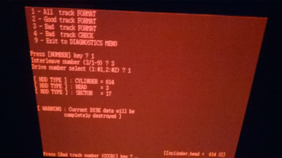
I wanted to try an orverlay software but I cant even format the dam drive.... (I dont care how much space I get from the drive , it will be probably 40-100mb) important thing is that I don't use the original (so I can save/keep)it as much as possible....

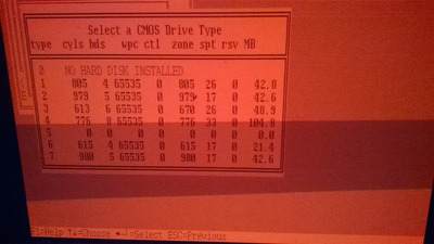
Wanted to do some overlaying - Ontrack Disk Manger (*or Fujistu Disk Manager ver 9.52) seems to give me more bios variants ... up to 104.8mb (in CMOS Dryve Type - 776cyls/8hds/33spt) ... problem is it dosent identify the WD 43AA. I have a small fujitsu ultra ata change mode utility v1.19 hdd app - UDMA100C.exe (or UDMA33/66/100.bat) that shows the drive as plugged in on ATA - but it shows it as an Unexpected Drive....

I would love to use this hdd , I dont want to waste more space with larger disk , and I dont have any smaller ones (may have a second disk that I could try but is 4gb also). (I dont want 2 much space , but I dont want to put a 40 gb or 80 or 160gb good drive in that bios only sees as 40-100mb)

I talked to someone that had a video on youtube and could confirm that he uses a large EDIE 160gb drive (I think it was WD? or seagate hmm need to chkeck - however he was limited by bios to format the 160gb drive to 100mb , but it worked! )

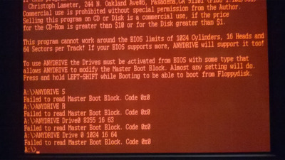
Theoretically there is an application (exe) called ANYDRIVE that should be able to extend your drives to up to bios limit of 1024cylinder 16 heads and 64 sectors per track but I don't know how to use it , and I suspect you need to have the drive already formated before using it.

P.S. Can we install Grub or use any tools from Hirens-Boot-15.2DVD? or 80286 is just to old for that stuff....

=======================================================================================================
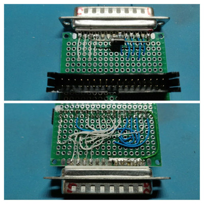
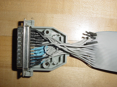
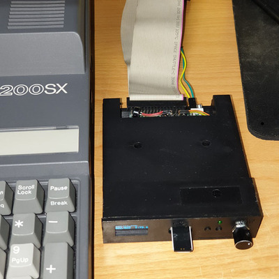
(have laptop from about 2008 maybe longer -got it from a friend as a trow/away-gift. At first floppy acted up but managed to start it just by cleaning and using it , even if it refused 5-20 first tries to see disks - now it works great 1.44MB/disk problem is I don't have only about 50 disks , hdd - 20mb was plugged in wrong and did not see it properly so it hung a lot of times , managed last year to fix that seeing the error - 2 pins from drive were not connected - was 1 row sideways plugged.)

L.E. I made some progress, but I am missing some steps I fear....
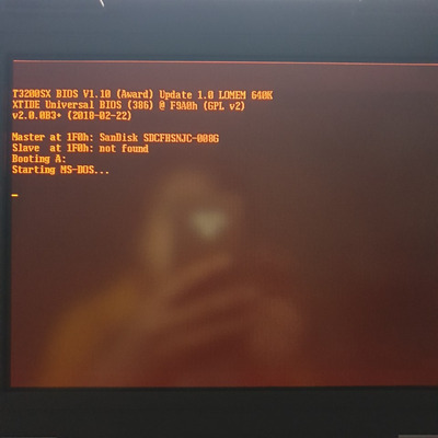
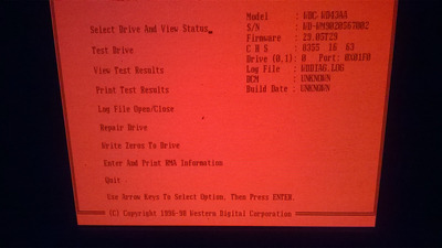
so WD utility seems ok with new drive in Toshiba.... WDTBLCHK sees it(even HDDID.exe) ,(as drv.1), and WDDIAG 2.60 runs great...
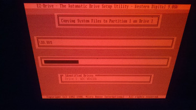
It Verifies Drive and I even Low formated , No errors found. Ez.exe Partitions it great (you can select fat16 or far32 1-4 partitions), even transfers files(Like Command.com) from Win95 boot disk or MS-DOS 6.22 Disk 1....
Problems is , it still get the error and not booting , maybe I need to do something additional step to this endevour.... problem is I an not quite sure what...
and what step I am skipping?!....

I cant find any EZ-Drive 9.06 Manual anywhere.... so I have to improvise as I am moving along....
When I do anything in EZ-Drive.EXE it wants to reboot the system , is there a /command to skip this?

Attachments

  • WP_20201222_002.jpg
    Filename
    WP_20201222_002.jpg
    File size
    969.02 KiB
    Views
    1434 views
    File license
    Public domain
  • WP_20201221_003.jpg
    Filename
    WP_20201221_003.jpg
    File size
    806.32 KiB
    Views
    1434 views
    File license
    Fair use/fair dealing exception
  • WP_20201221_001.jpg
    Filename
    WP_20201221_001.jpg
    File size
    1005.97 KiB
    Views
    1454 views
    File license
    Public domain
  • WP_20201220_003.jpg
    Filename
    WP_20201220_003.jpg
    File size
    742.27 KiB
    Views
    1454 views
    File license
    Public domain
  • WP_20201220_002.jpg
    Filename
    WP_20201220_002.jpg
    File size
    936.23 KiB
    Views
    1454 views
    File license
    Public domain
Last edited by ediflorianUS on 2020-12-22, 21:55. Edited 2 times in total.

My 80486-S i66 Project

Reply 378 of 539, by my03

User metadata
Rank Member
Rank
Member

I guess it complains simply because it will not recognize anything other than the (three?) Conner models that it would actually support when you use the original bios (i assume you don't use a modded bios?).

I use AnyDrive on a different 286 (Its a Victor/Sirius 286P) successfully but i don't think that model is as locked down as the Toshibas. But i "think" i saw someone (in the middle of this thread) that had some modded bios also for your model (look for it) and with luck, that version removes the whitelist...

Reply 379 of 539, by ediflorianUS

User metadata
Rank Member
Rank
Member
my03 wrote on 2020-12-22, 16:52:

I guess it complains simply because it will not recognize anything other than the (three?) Conner models that it would actually support when you use the original bios (i assume you don't use a modded bios?).

I use AnyDrive on a different 286 (Its a Victor/Sirius 286P) successfully but i don't think that model is as locked down as the Toshibas. But i "think" i saw someone (in the middle of this thread) that had some modded bios also for your model (look for it) and with luck, that version removes the whitelist...

So it needs a bios update ... hmm... probably you also need to pull the chip to do that ... I am great but I am not that great of a user...
I felt that some steps I skipped by mistake , and hoped that I can remediate(redo) those steps....

If i wont succeed(classic way) I will probably abandon my upgrade and restore factory drive....

Reading other posts about EZ-Drive , I gathered there should be a setting Type 9 in bios ? ”If you system bios dose not have auto config or userdefind, select Type 9” ...

My 80486-S i66 Project