VOGONS


First post, by quicknick

User metadata
Rank Oldbie
Rank
Oldbie

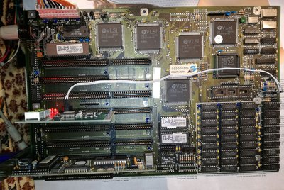
Earlier this month i got this board as part of a lot of 5 defective boards. I've managed to repair 4 of them until now but this one proves to be kind of stubborn.

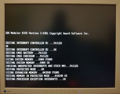
After neutralising and cleaning the corrosion from the battery i powered up the board, it seemed to work just fine but didn't respond to keyboard input. After some more reboots i noticed that every now and then, like once in five attempts, the board does skip the memory test when pressing the ESC key, and also displays a "Keyboard error" message if i keep any key pressed during a reboot.
But that's just about all it recognizes from keyboard and i've never been able to get past the "CMOS system options not set / checksum failure / display type mismatch / press F1 to continue" screen. It doesn't react to F1 or ctrl-alt-del or any other key.
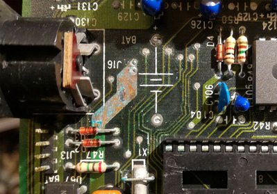
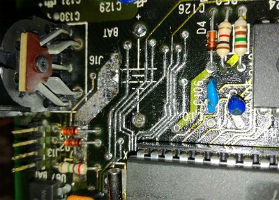
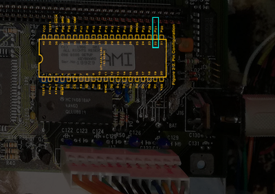
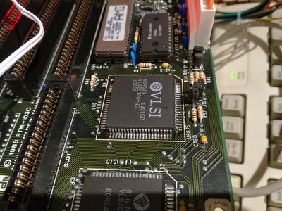
I have tinned with solder all the traces affected by corrosion and checked multiple times their continuity, including the vias that go through the board and everything checks ok. Also tried with other (known good) AMI keyboard controller, still same results. Even changed the keyboard controller socket, as it was a bit corroded.
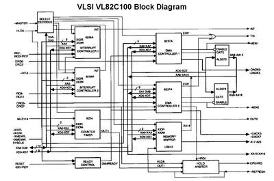
As a last resort I swapped the AMI bios and keyboard controller with Phoenix ones from another board with the same VLSI chipset, and in this combination the board hangs with some beeps and code 22 on my POST analyzer, which according to the books 😀 stands for "Test 8742 keyboard controller".

Any ideas / suggestions on what might be causing this kind of behaviour?

dtk_board.jpg
Filename
dtk_board.jpg
File size
819.18 KiB
Views
1422 views
File comment
The Board
File license
Fair use/fair dealing exception
dtk_before.jpg
Filename
dtk_before.jpg
File size
504.5 KiB
Views
1422 views
File comment
Before
File license
Fair use/fair dealing exception
dtk_after.jpg
Filename
dtk_after.jpg
File size
639.46 KiB
Views
1422 views
File comment
After
File license
Fair use/fair dealing exception

Reply 2 of 14, by Predator99

User metadata
Rank l33t
Rank
l33t

Nice board and nice repair! What tools did you use for this? Looks better than a wire 😉 Did you remove all green corrosion before applying the solder?

How does it look on the bottom side? Are you sure you didnt introduce a short?

Do the keyboards LEDs flash when powering up?

What error message do you get when powering up without a keyboard bios?

Reply 3 of 14, by derSammler

User metadata
Rank l33t
Rank
l33t

What you describe is *exactly* how my Headland HT12 286 mainboard behaves when no or a flat battery is present. Add a new battery, give it a few minutes, and then try again. It will most likely work without any issues then.

Reply 4 of 14, by quicknick

User metadata
Rank Oldbie
Rank
Oldbie

Thank you for your input!
@Auzner, derSammler - i will try fitting a battery, hopefully later today if i have some spare time, and i will post here the results.
@Predator99 - at first i used vinegar to neutralize the spill, then a local isopropyl bath to remove the vinegar. The board was very clean so i didnt have to scrub it entirely with isopropyl. After that i powered it up for the first time, it behaved like described. After that i removed some components (keyboard connector, 2 diodes, 1 resistor, clock crystal and variable capacitor) then i used the tip of a very sharp razor to scrape away from the affected traces all the corrosion/oxidation and remains of the green lacquer (solder resist i think it is called). After that i proceeded to coat all exposed copper with flux then applied solder with my soldering iron. Nothing fancy. I didnt have to use wire because no trace was broken. I dont think i have any shorts, because the board is behaving exactly as it did before my intervention. At a later time i also removed the keyboard controller socket, suspecting there was some damage to the traces below it. There wasn't any, but i fit a new one anyway since it was a bit corroded (and i removed it in tiny pieces 😁 )
As a side note, your threads about Suntac 286 motherboards kind of made me hungry for those, so here i am... partly thanks to you 😀

Edit: forgot to mention keyboard LEDs behaviour. With the original AMI bios/KBC, the leds blink right after the memory test (i think they should blink immediately after power on). With Phoenix chips, the leds blink at power on and then i get 3-1-3 beeps and code 22 on the display, all of these within a second or so.

Reply 5 of 14, by Predator99

User metadata
Rank l33t
Rank
l33t

"...then applied solder with my soldering iron."

This is the interesting part. What soldering iron do you use? With my equimpment I would not be able to solder such fine traces...

Thanks, did you also buy a Suntac?

With your problem - dont know. Lets wait for the result with battery.

Reply 6 of 14, by Auzner

User metadata
Rank Member
Rank
Member
Predator99 wrote:

With my equimpment I would not be able to solder such fine traces...

quicknick wrote:

i proceeded to coat all exposed copper with flux then applied solder with my soldering iron.

The traces were still good on the motherboard. With flux on the copper traces, heat from the iron will let the solder just flow to those parts. It will basically paint itself down neatly on the copper. Rosin core solder and a flux pen help do the job.

Reply 7 of 14, by quicknick

User metadata
Rank Oldbie
Rank
Oldbie

As Auzner said. I actually used old-fashioned rosin flux, which i melted with the soldering iron on minimum heat and deposed all over the affected area, then at around 350 degrees C i have tinned the tracks. I use a DYI (not buit by me but bought from someone that builds them) soldering station for most of the stuff, and a non thermo-controlled, 40-watt iron mainly for desoldering stuff.

I had just enough time to connect an external 6-volt battery pack to the motherboard's header, it still doesn't work.

About the errors when booting without KBC. When using the Phoenix bios, i get the same error code 22 with or without the controller. Swapped back to the original AMI bios, and although i am pretty sure that initially the board was completely dead when starting without KBC, now if i do that it displays a "8042 gate A20 error" and gives continuous and rather annoying beeps.

Reply 8 of 14, by Auzner

User metadata
Rank Member
Rank
Member

That's an issue with the 286 high memory mode because of address A20 line shared with the keyboard. 8042 is the original IBM keyboard controller. Will see if there's a solution if it's not connection related.
http://zet.aluzina.org/images/d/d4/8042.pdf
https://www.win.tue.nl/~aeb/linux/kbd/A20.html
http://wiki.osdev.org/A20_Line

What happens if you pull out enough DRAM to get to 1MB or less and then try booting? (Each of those chips in the photo appear to be 128kB)

Triple-check the connection to this output pin:

p21.png
Filename
p21.png
File size
410.1 KiB
Views
1305 views
File license
Fair use/fair dealing exception

Reply 9 of 14, by quicknick

User metadata
Rank Oldbie
Rank
Oldbie

The installed ram is 1MB (and that's the maximum, according to stason.org). KBC pin 22 goes to pin 11 of the VL82C102 memory controller (A20 Gate - Used to select the proper value for address bit 20).

I spent my evening tracing all the pins from the KBC and comparing with a working board with the same chipset (Unidentified MBVLSI-168 B). There are some differences but nothing too serious:

- pin 31 is connected to GND on the working board but left floating on the bad one, pulled it down with 100 ohm resistor and it didn't change anything.
- on the good board there are 4 jumpers that can short pins 23, 27, 30, 32 to something that i haven't identified yet (it's not +5v or gnd), here's what stason.org page on that board says about these jumpers: Note: Make sure that the BIOS and the keyboard controller are compatible before shorting a controller pin for speed change via software.
- there are some differences in the supporting circuitry (bad board has quite a few more 74LS chips), so for example pin 21 of the KBC that on the good board connects directly to pin 9 (Reset) of the VL82C101 system controller, on the bad board goes first through not one but two buffers from a 7407 chip (and there is something that connects in between the two buffers).

Tomorrow i'll do some more comparisons with the boards powered on, maybe i'll find a stuck line or something like that.

Reply 10 of 14, by quicknick

User metadata
Rank Oldbie
Rank
Oldbie
quicknick wrote:

Tomorrow i'll do some more comparisons with the boards powered on, maybe i'll find a stuck line or something like that.

Had no time for that, and besides i think it might be futile without an oscilloscope or logic analyzer (only have a couple of multimeters).
For a quick and dirty test i replaced once again the bios/kbc with some Award ones from (another) working board. This one seems to give the most details about the problem:

errors.jpg
Filename
errors.jpg
File size
193.25 KiB
Views
1223 views
File license
Fair use/fair dealing exception

After displaying the above, the system hangs with Code 26 on the POST card. The CMOS battery failed message keeps appearing even when i connect an external battery pack and the RTC chip receives power. I'll keep searching, but after triple-checking all connections from the kbc and all the corroded/repaired traces i'm thinking more and more that the problem lies elsewhere (chipset, support chips).

Reply 11 of 14, by quicknick

User metadata
Rank Oldbie
Rank
Oldbie

Found the problem, it was inside the VL82C100 peripheral controller. Took my chance and transplanted the chip from another board which had it socketed - it was so tight that i couldn't extract it with the PLCC tool, i only managed to chip away one corner of the package (hence the ugly diagonal scratch). I had to desolder the socket with the chip still in it and then tear it to pieces.

I also tried to solder a PLCC84 SMD socket on the DTK board, to have the chip easily removable in case it didn't solve the problem, but found this to be impossible: the solder pads on the board didn't extend inwards as much as i needed to get a reliable solder joint. Fortunately the problem is now gone so there's no need to remove it again. For the removal of the defective chip i long planned to get a hot air station, but in the end took it off with only soldering iron and copper braid.

So now the donor board is in a non-working state, but i'm okay with that. It's an Essex Electric for which i cannot find any documentation online, it has quite a few undocumented jumpers and also some options like onboard floppy controller (missing) and onboard serial ports. I know i can easily bring it back to life if i find a replacement VL82C100 chip - if someone has one, please contact me.

dtk_repaired.jpg
Filename
dtk_repaired.jpg
File size
391.04 KiB
Views
1115 views
File comment
Working!
File license
Fair use/fair dealing exception

Reply 13 of 14, by quicknick

User metadata
Rank Oldbie
Rank
Oldbie

Well, i got myself a new soldering/desoldering station (ZD-917) a couple of weeks ago, and that reignited my interest in my broken boards. I already found a toasted MC14069 hex inverter on this board, but unfortunately after replacing it the board is still as dead as before.

On the DTK board i checked all 14 or so logic chips (desoldered them using the station, tested them in the TL866CS programmer) and all were ok, so i took the risk of exchanging the peripheral controller. I wasn't 100% sure that it is faulty, it was more like a hunch. I must say that the Award bios helped me with that - check that "Interrupt controller #1 failed" message a couple of posts back. And since the interrupt controllers are inside the VL82C100...

82C100.png
Filename
82C100.png
File size
54.95 KiB
Views
1070 views
File license
Fair use/fair dealing exception

Reply 14 of 14, by Tiido

User metadata
Rank l33t
Rank
l33t

Nice work !

I actually have the VL82C100 and other chips belonging to the set, but I have no clue if they work or not. All were salvaged from a dead 286 board many years ago.

T-04YBSC, a new YMF71x based sound card & Official VOGONS thread about it
Newly made 4MB 60ns 30pin SIMMs ~
mida sa loed ? nagunii aru ei saa 😜