Reply 100 of 124, by mpe
Rank
Oldbie
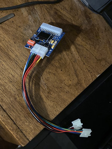
My setup is 24V/5A DC power source + 80W ATX pico PSU + ATX2AT. Like this

But I will try to simplify it and use regular ATX PSU just to be sure.
My setup is 24V/5A DC power source + 80W ATX pico PSU + ATX2AT. Like this
But I will try to simplify it and use regular ATX PSU just to be sure.
Let's leave out my special firmware for a moment. Once I experienced said problems I flashed the original back to rule that out as the cause. I tested both my firmware and the original one on my 486 test rig and it works fine. The only thing I changed after that was the mainboard the ATX2AT was connected to: A P55T2P4 with an Pentium MMX 233. Also for testing I use either the onboard switch or the Configuration Tool. There's no external switch connected right now.
I sent an email to Sam and he assured me that this is supposed to work. He proposed downclocking the CPU for testing but I outright removed the whole thing and guess what - it still triggers.
How did you exactly measure that?
I used my multimeter directly on the P8P9 socket. The Ohms take some time until they stabilize, I suppose because there's caps charging up.
Do you have another device to measure the amperage when switching on?
Well, my multimeter. I see two issues with why I tried to avoid this:
* My multimeter fused for 10A. If the ATX2AT is correct the current on 5V is bigger than 8A. I'm afraid I might trigger the fuse. Depends on the length of the spike though. The 10A fuse of the ATX2AT didn't trigger yet, but that might caused by the fast reaction time of the "virtual fuse".
* It's rather complicated to introduce the meter into the circuit.
Does the board work with the AT supply? Does anything get unusually hot?
The last time I turned this computer on was more than half a year ago. I'm a little bit afraid to use the original PSU. That's also why I haven't figured out if anything gets hot.
I guess I have two options: Check the actual power draw with my meter and/or run the board without the ATX2AT and figure out what gets hot by either using IPA or my hand.
I wanted to investigate the firmware if perhaps the protection can be make less aggressive. Need to investigate how to change settings as I am on a Mac so cannot use the configuration tool.
That's definitely possible. The relevant code for 5V is this:
if (cur_5v > 9.0 || ((cur_5v > max_5v) && !slowblow) || ((cur_5v > (max_5v * SBOS5V)) && slowblow)) {// if current > 9.0A OR fast blow mode and current limit exceeded OR slowblow and current limit + 75% => trigger immediatlyocurrent5 = true;} else if (cur_5v > max_5v && slowblow) {// slowblow and current limit exceeded. Allow SB_DELAY msec grace period before trippingif (blowtimer5v == 0) {blowtimer5v = millis();} else if ((millis() - blowtimer5v) > sb_delay) {ocurrent5 = true;}}
The first if statement will trigger OCP immediately if (5V is above 9A) or (fastblow is enabled and 5V is above the limit set) or (slowblow is enabled and 5V is 75% above the limit set)
The second if block only triggers OCP if slowblow is enabled and 5V is above the limit for longer than grace period set which is 150ms by default but can be changed with the configuration tool to up to 500 ms.
To hardcode the limit on 5V change this line:
max_5v = (float)EEPROM[cset + 0x10] / 20.0;
To hardcode the delay change this line:
// Set SlowBlow Delay from EEPROMsb_delay = (unsigned int)EEPROM[4] * 10;
However make sure you don't blow the ATX2AT fuses with your changes.
But you ARE using an ATX PSU, right?
Yes, an Seasonic Focus Gold 450W. I don't think the PSU is the culprit as the ATX2AT triggers before the PSU.
My setup is 24V/5A DC power source + 80W ATX pico PSU + ATX2AT.
Uhm... make sure that PSU is up for the task. 5V was way more important back then as it is now. Can this PSU provide 5A on the 5V line?
My setup is 24V/5A DC power source + 80W ATX pico PSU + ATX2AT.
Uhm... make sure that PSU is up for the task. 5V was way more important back then as it is now. Can this PSU provide 5A on the 5V line?
Yes it can do 6A @5V. Even more peak load. It has its own protection firing at 8.4A. Should be fine for 486/Pentium motherboards. But will retest with a beefier PSU. Work fine when not using atx2at though....
xsecret wrote on 2018-05-09, 18:41:As a CPU collector since 15+ years, I'm trying to keep at least a working platform (motherboard/memory/storage) for every CPU fa […]
As a CPU collector since 15+ years, I'm trying to keep at least a working platform (motherboard/memory/storage) for every CPU family. I have a lot of 8088/286/386/486 motherboards but I'm still trying to find some rare ones (EISA, SMP, etc.). They all works with the infamous P8/P9 power connectors. These boards are now becoming outrageously expensive, so it often worth the time to fix dead ones (replacing caps, etc.) or at least to avoid ruining them when they're in working condition.
Some weeks ago, I fried a nice 486 motherboard I got in a scrap lot at first boot. Some capacitors were shorted and my ATX PSU, coupled with a regular passive ATX2AT adapter, led to massive damage (burnt traces). That short was not "short enough" to trigger the (very large) PSU overcurrent protection. The motherboard was FUBAR by the time I noticed something went wrong and manually switched off the power (within 3/4 seconds).
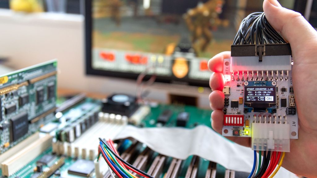
So, I created a "Smart" ATX2AT Converter, featuring fully-programmable electronic fuses. I also added a small OLED display for monitoring purpose, a -5V regulator to regenerate that missing voltage (required by some sound cards) and some additional filtering capacitors. The project will ultimately be open-source and can be adapted for any other retro-platform that require -12/-5/+5 and/or +12V.
Much more technical details are available on this page: https://x86.fr/atx2at-smart-converter/
I'll be happy to hear your thoughts and suggestions about this project. 😀
Some friends in the CPU collectors' community already expressed an (unexpectedly) strong interest for that adapter, so maybe some fellow retro-computing addicts here might also be interested. If we're only a few to want one, I'll assembled them manually, but if we're more than a few, I can consider having them built by a fab to reduce costs.
PS: crappy video here: https://www.youtube.com/watch?v=3eRXQ0c1YZg
Can I get one? 😀 maybe two?
mpe wrote on 2021-01-11, 11:41:My setup is 24V/5A DC power source + 80W ATX pico PSU + ATX2AT. Like this […]
My setup is 24V/5A DC power source + 80W ATX pico PSU + ATX2AT. Like this
But I will try to simplify it and use regular ATX PSU just to be sure.
That’s cool 🤣
Is there still a change to order two or three of these?
Anyone still wanting one or more of these might find it easier to contact xsecret through the CPU-World forums (https://www.cpu-world.com/forum/), where he is more active. I'm not sure whether he has more, or plans to build more, or even has them on eBay, but you are more likely to get a response there.
See my graphics card database at www.gpuzoo.com
Constantly being worked on. Feel free to message me with any corrections or details of cards you would like me to research and add.
debs3759 wrote on 2022-01-02, 00:31:Anyone still wanting one or more of these might find it easier to contact xsecret through the CPU-World forums (https://www.cpu-world.com/forum/), where he is more active. I'm not sure whether he has more, or plans to build more, or even has them on eBay, but you are more likely to get a response there.
Thanks!
Atx2at dip settings (incase homepage ever goes offline)
I’m not quite sure how to interpret it though…

Edit: okay,
You can change 1,2,3 with the psu plugged in (but turned off beleive it or not) and it will show on the screen the setting for each combination you enter on the dip switches for 5v. And same for 12v on 4,5, (all on) is the highest setting at 8a 5v, and 4.75a 12v
I guess I will select these high settings, plug it in and monitor my amps, then turn it off and select a setting that is lowest that I think won’t trip under normal operation.
The intigrated power button is nice and works well. The display seems to work nice and display what you want it to. So far so good! 😀
Switch 6 is for fastblow,, discription is a little vague, but it sounds like something that I would want on?? Yet says for developer only? Would be interested in a more detailed explanation for this.
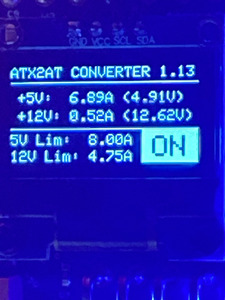
First power up! (8a 5v, 4.75a 12v)
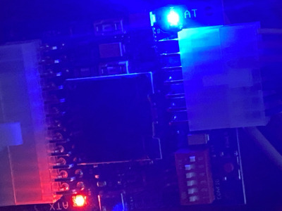
It didn’t go well,
Here is the configuration,
And here is what happened,
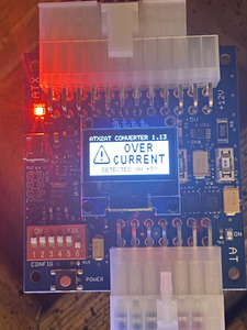
And here is what I had to do to make it go,
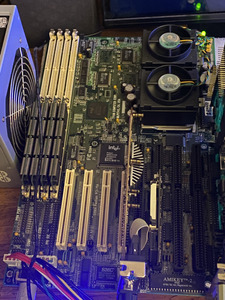
It seems like two cpus may be a tad more than this was deaigned for.🤔
I wonder if custom firmware can add higher amperage options..?
I suppose I could have asked him about max amperage before ordering, but it didn’t even occur to me at the time 🤣. I guess I just assumed it would have a option high enough for whatever AT mobo I wanted to run. Prior to actually using this device I had no idea what amperage I would be expecting on the various rails though, and not much way of finding that out. Without a device like this or the motivation to use a clamp amp.
Anyway, in this config it spikes around 7a during post and settles around 5a
Next I will try some system loading to see the effect.
For this, I will remove the xt-IDE and hook up drives. Note that drives do not go through the atx2at so don’t add to the load sensed by the atx2at except for whatever goes over the ide cable.
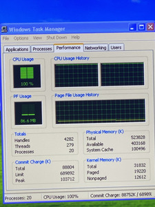
Update, windows xp failed to boot with real drives and no xt-ide. It kicked out again on 5v over current.
I will try under volting the cpu(s) now. These are hand picked ones that will post in the 300-333mhz range so undervolting them will likely be stable at 233. I will try 2.25v
Edit: it booted!
It’s hovering around 7a😬
Stressing the cpus doesn’t seem to add much to the actual load. A little bit, I mean, but not much.
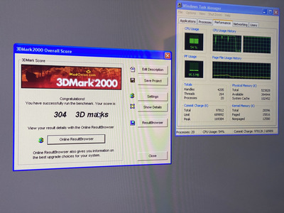
Next I will stress cpu 1 (#2) by selecting affinity in task manager, and run 3dmark with the other cpu (#0)by selecting affinity in task manager.
Edit: that did it, pushed it over the edge.. grr.
I have one lower voltage setting I can try. 2.15v the only setting after that is 1.2v and that’s unlikely to work.
Edit:
2.15v appears to be (barely) working, past this, I can underclock (where is the fun in that..) or I can drop to one cpu, (a k6 3+ 400) but that’s getting away from the point.
While I believe that this voltage will stably run these cpus, I don’t think the same can be said of other 233s as I have said these were hand picked from a large lot of 233s.
Also, if I plug in a few usb items or cards I’m back to square one. 🤔
Here is to hoping that the firmware will allow the addition of some higher settings. Fingers crossed.
Edit: after some run time I noticed that the screen turned off (everything is still running normally, nothing has changed, bench still running) and I’m not sure how to turn it back on….🤔
Edit: successful run,
Btw, screen turned back on on system power off. Which is kinda the opposite of what I wanted it to do.. it seems to have some sort of time out that you can’t wake it from except to reset the computer… needs a wake button🤷♂️
I wanna take the time to say that this device, the creator, and project is/are awesome, and I’m happy to have it even if I have criticisms. I think input and reports like this are helpful for helping a product evolve.
Reading the whole thread again, some comments,
I agree about the suggestion to make the output simply use a atx style layout. But understand the parts dificulties and desire to make it universal. But I really want something like this for my atx mobos as well. (Like my k6 3+ build) perhaps the answer is not one device, but several models? A easy source for atx plugs is old PSUs. The pigtails could attach to the board via a screw terminal block, spade terminals, direct solder (though, I don’t like this option because of metal fatigue)
The device needs a case or a better way to mount it, this is 100% true. A 3d printed case is definitely needed.
Thick double sided foam tape is definitely one way that should work, but it’s a problem as soon as you need it elsewhere.
A metal bracket that could attach to the rear 80mm fan seems like a good place to start with a mounting idea.
gordon-creAtive.com wrote on 2021-01-11, 13:40:Let's leave out my special firmware for a moment. Once I experienced said problems I flashed the original back to rule that out […]
Let's leave out my special firmware for a moment. Once I experienced said problems I flashed the original back to rule that out as the cause. I tested both my firmware and the original one on my 486 test rig and it works fine. The only thing I changed after that was the mainboard the ATX2AT was connected to: A P55T2P4 with an Pentium MMX 233. Also for testing I use either the onboard switch or the Configuration Tool. There's no external switch connected right now.
I sent an email to Sam and he assured me that this is supposed to work. He proposed downclocking the CPU for testing but I outright removed the whole thing and guess what - it still triggers.
How did you exactly measure that?
I used my multimeter directly on the P8P9 socket. The Ohms take some time until they stabilize, I suppose because there's caps charging up.
Do you have another device to measure the amperage when switching on?
Well, my multimeter. I see two issues with why I tried to avoid this:
* My multimeter fused for 10A. If the ATX2AT is correct the current on 5V is bigger than 8A. I'm afraid I might trigger the fuse. Depends on the length of the spike though. The 10A fuse of the ATX2AT didn't trigger yet, but that might caused by the fast reaction time of the "virtual fuse".
* It's rather complicated to introduce the meter into the circuit.Does the board work with the AT supply? Does anything get unusually hot?
The last time I turned this computer on was more than half a year ago. I'm a little bit afraid to use the original PSU. That's also why I haven't figured out if anything gets hot.
I guess I have two options: Check the actual power draw with my meter and/or run the board without the ATX2AT and figure out what gets hot by either using IPA or my hand.I wanted to investigate the firmware if perhaps the protection can be make less aggressive. Need to investigate how to change settings as I am on a Mac so cannot use the configuration tool.
That's definitely possible. The relevant code for 5V is this:
if (cur_5v > 9.0 || ((cur_5v > max_5v) && !slowblow) || ((cur_5v > (max_5v * SBOS5V)) && slowblow)) {// if current > 9.0A OR fast blow mode and current limit exceeded OR slowblow and current limit + 75% => trigger immediatlyocurrent5 = true;} else if (cur_5v > max_5v && slowblow) {// slowblow and current limit exceeded. Allow SB_DELAY msec grace period before trippingif (blowtimer5v == 0) {blowtimer5v = millis();} else if ((millis() - blowtimer5v) > sb_delay) {ocurrent5 = true;}}The first if statement will trigger OCP immediately if (5V is above 9A) or (fastblow is enabled and 5V is above the limit set) or (slowblow is enabled and 5V is 75% above the limit set)
The second if block only triggers OCP if slowblow is enabled and 5V is above the limit for longer than grace period set which is 150ms by default but can be changed with the configuration tool to up to 500 ms.
To hardcode the limit on 5V change this line:
max_5v = (float)EEPROM[cset + 0x10] / 20.0;To hardcode the delay change this line:
// Set SlowBlow Delay from EEPROMsb_delay = (unsigned int)EEPROM[4] * 10;However make sure you don't blow the ATX2AT fuses with your changes.
But you ARE using an ATX PSU, right?
Yes, an Seasonic Focus Gold 450W. I don't think the PSU is the culprit as the ATX2AT triggers before the PSU.
My setup is 24V/5A DC power source + 80W ATX pico PSU + ATX2AT.
Uhm... make sure that PSU is up for the task. 5V was way more important back then as it is now. Can this PSU provide 5A on the 5V line?
Gordon, you seem like you might be able to help me figure out a firmware mod? Personally, I’m quite clueless on this… not even sure how to flash this thing… doesn’t fit in my chip programmer 🤣. 😂
Sphere478 wrote on 2022-02-04, 05:38:Switch 6 is for fastblow,, discription is a little vague, but it sounds like something that I would want on?? Yet says for developer only? Would be interested in a more detailed explanation for this.
on https://x86.fr/atx2at-smart-converter/
there's a section called What’s really “Smart” in the ATX2AT Smart Converter?
which details the function of slow/fast blow.
it's basically what it says, fast blow acts like a fast fuse, slow blow acts like a slow fuse.
Right to repair is fundamental. You own it, you're allowed to fix it.
How To Ask Questions The Smart Way
Do not ask Why !
https://www.vogonswiki.com/index.php/Serial_port
weedeewee wrote on 2022-02-04, 09:38:on https://x86.fr/atx2at-smart-converter/ there's a section called What’s really “Smart” in the ATX2AT Smart Converter? which d […]
Sphere478 wrote on 2022-02-04, 05:38:Switch 6 is for fastblow,, discription is a little vague, but it sounds like something that I would want on?? Yet says for developer only? Would be interested in a more detailed explanation for this.
on https://x86.fr/atx2at-smart-converter/
there's a section called What’s really “Smart” in the ATX2AT Smart Converter?
which details the function of slow/fast blow.it's basically what it says, fast blow acts like a fast fuse, slow blow acts like a slow fuse.
Thanks 😀 I see that now, I was looking lower down next to the dip settings before.
The explanation above where you referenced is very adequate!
Sphere478 wrote on 2022-02-04, 08:02:Gordon, you seem like you might be able to help me figure out a firmware mod? Personally, I’m quite clueless on this… not even sure how to flash this thing… doesn’t fit in my chip programmer 🤣. 😂
Yeah, but I'm pretty busy right now and far away from my ATX2AT. It's been some time but I'm 100% sure you don't need a dedicated programmer. As far as I remember you can attach the USB lead to your PC and use it like an Arduino.
gordon-creAtive.com wrote on 2022-02-20, 07:22:Sphere478 wrote on 2022-02-04, 08:02:Gordon, you seem like you might be able to help me figure out a firmware mod? Personally, I’m quite clueless on this… not even sure how to flash this thing… doesn’t fit in my chip programmer 🤣. 😂
Yeah, but I'm pretty busy right now and far away from my ATX2AT. It's been some time but I'm 100% sure you don't need a dedicated programmer. As far as I remember you can attach the USB lead to your PC and use it like an Arduino.
Okay. I guess I will google that, I’ve never used an ardrino. I’ve of course heard of them though 😀
Btw, update, I did end up trying this on one cpu. A k6-3 (not plus) at 2.2v 400mhz and I actually had a over current event with it also. (Normal operation was beyond the current limits of the device)
Yeah, I really need a few more amps from this thing haha
You can probably just use the tool to flash the firmware or configure settings :
https://github.com/x86fr/ATX2AT-Smart-Converter
Anyway, i really don’t recommand more than 8A. The ATX2AT has been built for P5 max. If you can find an ATX motherboard for your CPU, the ATX2AT SC is probably not the solution.
Hi! Can anybody help out with question (seems like error) in ATX2AT BOM list? And/or knows, how to find contact with xsectet?