First post, by ruthan

Rank
Oldbie
- Rank
- Oldbie
Hello,
i bough Lucky star 5mvp3 4.0 SS7 MB, i have problem to get PS/2 mouse to run.. it arrived without PS/2 header, so i salvage one from other machine (where it was working fine), but wiring is probably not compatible, i didnt found PS/2 mouse Bios option is probably always enables.. or dead, if is not problem with wiring, but i doubt it.
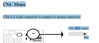
In manual is only very bad description of header connector..
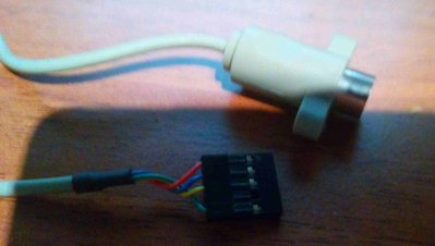
My cable:
Im old goal oriented goatman, i care about facts and freedom, not about egos+prejudices. Hoarding=sickness. If you want respect, gain it by your behavior. I hate stupid SW limits, SW=virtual world, everything should be possible if you have enough raw HW.


