VOGONS


First post, by parhelia512

User metadata
Rank Member
Rank
Member

Hello all ! 😀

I have a QDI Winnex 2E which is a i810E Slot 1 motherboard.
The motherboard is posting fine but, as soon as the board is trying to load the OS, the system freezes or reboot.
I've tried other CPU, RAM, adding a PCI Vga card but the result is the same.

I don't know if it can help but even in the BIOS, the VGA output from the onboard chipset is unstable.

Thanks for your help ! 😀

Reply 1 of 35, by dionb

User metadata
Rank l33t++
Rank
l33t++

VGA output unstable? That suggests analog circuitry issues, and with a 1999 board that probably means bad caps - and this board certainly has enough of them...

Do you have a good pic of the area of the board between CPU slot and the external connectors?

Now, not booting may or may not be related. If caps are OK (or you replace the dead ones), it could be a BIOS issue. Fortunately this board has a socketed PLCC EEPROM. If you have some way to flash EEPROMs, you could try to re-flash the BIOS.

Alternately, it could that both unstable video and boot issues stem from a bad power supply. Does this PSU work fine with other boards?

Reply 2 of 35, by parhelia512

User metadata
Rank Member
Rank
Member

Hello Dionb and thanks for your answer.

Yes, VGA output has distortions (no artefact). I've tried to inspect capacitors. One off them looked inflated and i've replaced it (with no result), others seem fine.

I can see the windows 98 start screen and computer freezes. Sometimes, it will start scandisk and freeze.
It seems that using a lower power cpu (P3 667 vs P2 400) the board can sometimes go to Windows Safe mode...then freeze.

Power supply should be ok as it powers correctly an Athlon XP system too...

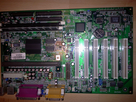
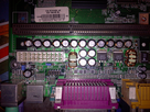
Here is a picture near the SLOT 1 :
1573456869-photo2985.png

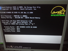
Sometimes, the board doesn't pass the POST and after disk recognition, the system freeze with a white line :
1573458208-photo2987.png

Thanks 😀

Reply 3 of 35, by dionb

User metadata
Rank l33t++
Rank
l33t++

Was the cap you replaced the same type as the others? If so, it's generally a good idea to replace all caps of the same type if one is visibly bad - they go bad internally long before they actually bulge or leak. The ones on the pic look good, but that's still no guarantee. The fact your problems are intermittent and dependent on CPU power draw strongly suggest problems somewhere in the board's voltage regulation or PSU, but if the PSU can handle an AthlonXP it should be able to do this stuff with no trouble whatsoever, so I suspect the board's electrics.

Reply 4 of 35, by parhelia512

User metadata
Rank Member
Rank
Member

Yes, it was one of the 16 (!!!) capacitors near the SLOT1 connector.
Is there a way to test a capacitor once unsolded ?
Have tried with anoter PSU and the card behaviour the same.
I'm able to replace capacitors but my electronical skills stop there ! 😀

Thanks again for your help !

Reply 5 of 35, by _UV_

User metadata
Rank Newbie
Rank
Newbie

On your first picture we can clearly see 2 mosfets CEB703AL.
I found image of similar looking mainboard, at least i'ts found by the provided name
http://www.rainbow-software.org/images/hardware/p6i810w2.jpg
It have 3-4 same looking elements, they could be linear voltage regulators or LDO. Check voltages on them. Make detailed pictures of entire board and it's interesting parts.

Reply 6 of 35, by Errius

User metadata
Rank l33t
Rank
l33t

I wonder if the OP could post some pictures of the entire board? I was looking for images of this board a while ago but couldn't find any in decent quality.

Is this too much voodoo?

Reply 7 of 35, by shamino

User metadata
Rank l33t
Rank
l33t

Given the way your board is behaving, I think it may be interesting to check all the voltages that you can with a multimeter. If you have a meter and want more detail on how to do those measurements, let me know.

I agree that you probably have other bad caps that aren't visibly obvious. As dionb mentioned, not all bad caps bulge and if they do bulge, it only happens long after they already failed. Ideally they should all be replaced, or at least all that are the same type or in the same circuit. The caps along the CPU slot and the 4 in a square arrangement behind them are probably connected to the 5V input of the VRM and to the Vcore output to the CPU, and those would usually be the most susceptible to failure. But there's a good chance of other bad ones scattered around the board also.

Bad caps sometimes fail short, and if that's happening, it could be putting a strain on the PSU. Caps heading towards a short condition, or simply having high ESR, can also put strain on components of the motherboard.

Is there a way to test a capacitor once unsolded ?

You can measure capacitance with a multimeter, but there's a limit on how much capacitance they can measure and many of them won't handle a cap of that size.
There's also more specialized tools that can measure a cap's ESR (Equivalent Series Resistance), which should be very low on a good cap used for Vcore. ESR usually shoots way up as a cap fails, and high ESR prevents the cap from doing it's job (regardless of what the capacitance is). But a multimeter won't measure ESR.

Reply 8 of 35, by parhelia512

User metadata
Rank Member
Rank
Member

Thanks all for trying to help me

So, i understand that the first step is to change capacitors. If i change it, do they have to be exactly the same ?

Shamino, yes, thanks, would be a pleasure to follow your steps to make some measurements as i'm a really noob in electronics.
My multimeter is a basic one.

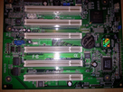
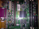
Here are some pictures of the board :

1573846543-photo3012.png

1573846588-photo3013.png

1573846591-photo3014.png

Thanks 😀

Reply 9 of 35, by jcarvalho

User metadata
Rank Member
Rank
Member

+1 for replacing all the caps near cpu slot, if one of them fails, the others will be bad also, they have all the same age.
Also clean the slot pins and cpu. If you can try another one

Reply 10 of 35, by parhelia512

User metadata
Rank Member
Rank
Member

In fact, i'm not sure the one i replaced was bad but it seemed a little inflated and the strange thing is that it was unsolded at back (the motherboard was inside a case in a cold room. PC has not been powered on for 10 years i think).
Tested with P2 400 / P3 450 / P3 667. Best results with the P3 667.

Reply 11 of 35, by _UV_

User metadata
Rank Newbie
Rank
Newbie

Weak solder joints - cold joint, melt solder on each pint of big caps and chokes. Recap is a last hope 😀 as long as it can post and at least try to load something. Check voltages on mosfets near CPU and PCI1. If you can't at least check it with a finger, sure they would be hot, but must not cause blistering and if you may touch it for 10-20 sec mosfets should be fine otherwise they probably damaged or something causing short. You may do same procedure with every IC on the board.

WHat OS you trying to load, is it stable under BIOS or DOS for a long time (let's say 15-30 min is enough)? Run Quake or PCP benchmark for the same amount of time. If PC not freezing here at DOS, try to install Win98 and Windows XP, if you have problems with cache or RAM it will crash or freeze. If you have troubles after install with loading OS that is probably resource conflicts. If windows xp loads fine, you have issues with how Windows 98 interpret ACPI and trying to manage PCI IRQs.

Reply 12 of 35, by shamino

User metadata
Rank l33t
Rank
l33t

When measuring voltages, put the black probe (negative probe) into the end of one of the black wires of an unused hard drive connector. You can also put it on the PSU casing or the case of the PC somewhere.
Then touch the red probe to whatever you need to measure. If you need to measure something in a tight space and you're worried about accidentally shorting 2 points together, then wrap the probe with tape so that only the tip is exposed.
Check voltages while the system is running, and pay attention to whether the voltages are stable or if they seem to fluctuate with load.

I'm assuming your PSU has a unified +12V rail, but if it has separate rails then they each should be checked. Some PSUs can have a separate +12V supply for the ATX connector vs the drive connectors (and another for the 4pin/8pin connector, which this board doesn't use).

PSU +5V can be checked using an unused 4pin drive connector. Red probe goes to the red wire. Black can go to any ground as mentioned above. It's more accurate to use the black ground wires on the same connector as what you're measuring, but that's not necessary.
PSU +12V is at the yellow wire of the same unused drive connector.
To measure battery voltage, just put the red probe on the top of the battery. It shouldn't be the problem here but might as well check it.

PSU +3.3V is at an orange wire on the ATX power connector. To measure that, you can push the red probe into the back of the connector, sliding it next to the orange wire until it makes contact with the metal connector inside of the plastic housing.
PSU +5Vsb (standby) is at the purple wire of the ATX power connector. It can be measured the same as the 3.3V (orange).
If you want to check more directly the +5V and +12V supplies that are going to the motherboard, you can measure at the red and yellow wires of the ATX connector this same way.

Between the peripheral ports and the CPU slot are a pair of MOSFETs labelled:
CET
CEB7030AL
These are used by the voltage regulator IC to produce Vcore.
They have 3 legs at one side and a large metal tab at the other.
Put the red probe at the large metal tab of one of them, and then the other.
One of these will give you the +5V supply that's providing power to the Vcore regulator.
The other will give you the Vcore output that's powering the CPU. It should be steady and matching what your CPU is supposed to have.

I noticed in your picture there's a marking that says "VDIMM" in the area between the CPU and the RAM, next to the RAM slots and close to an electrolytic cap.
It's very near a couple of tiny surface mounted caps. I wonder if one side of either of those caps would be the DIMM voltage.
On many SDRAM boards, the RAM runs directly from the +3.3V PSU supply, but maybe this one is fancier. Sometimes the chipset runs from that also, but I don't know what voltage the i810 uses.

There is a tolerance to all these values, but that tolerance includes high frequency ripple that you can't see with a multimeter because it happens too fast.
Personally, I also think many boards are not reliable when you get to the lower range of what is "supposed" to be allowed.
So in practice, it's good (and normal) to see voltages that are just a tiny bit higher than the specified value, and which don't sag more than a tiny bit when the system is under a heavy load.

Tested with P2 400 / P3 450 / P3 667. Best results with the P3 667.

Interesting, the P3-667 should have the lowest power consumption, but it's also running at a faster FSB clock.

So, i understand that the first step is to change capacitors. If i change it, do they have to be exactly the same ?

They should be "Low ESR" types, preferably made by either Nichicon, Nippon Chemicon, United Chemicon, Panasonic, Rubycon, Sanyo, NIC. If you have to take 2nd hand caps from other old boards (which is not ideal), then you might not have those choices. In that case, then Teapo is usually okay. *Not* Tayeh, which people sometimes confuse them with.
The capacitance value (uF) should be the same, slightly higher is okay. The Voltage rating can be the same or higher, higher won't hurt anything.
Reply 13 of 35, by parhelia512

User metadata
Rank Member
Rank
Member

Wow ! Thanks a lot shamino !

I will try this during the week end and will let you know the results i will find.
Does the voltage results will help decide whether the capacitors are OK or not ?

Thanks for your help 😀

Reply 14 of 35, by shamino

User metadata
Rank l33t
Rank
l33t
parhelia512 wrote:

Does the voltage results will help decide whether the capacitors are OK or not ?

No, the voltage readings won't tell you much about the caps. Bad caps will allow significant voltage fluctuations but they're at such a high frequency that the meter won't show that. The meter can only update a few times per second at most, so it's just showing the average voltage over a longer period of time.

What the meter can show you is if the sustained/average voltages are what they should be, and whether they're sagging under a load. Those things can (and often do) turn up as problems, so if there's a detectable voltage issue then it would be important to identify it.

Based on the fact that you found a bad cap already, and the board runs a little better with a lower powered CPU (667MHz Coppermine), it sounds like the Vcore circuit on the motherboard might be suffering from bad caps. I would suggest replacing those caps regardless. Checking DC voltages is an additional, and in my opinion valuable troubleshooting step, but it's not related to the caps.

Reply 15 of 35, by parhelia512

User metadata
Rank Member
Rank
Member

Thanks for your answer.

I've checket the MOFSETs voltage :
- First one : 5V
- Second one : 2.2V
- Third one (near the AMR SLOT) : 3.5V
- Fourth one (near memory slot) 3.4 - 3.5v

Voltages seem stable.

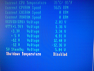
But i've noticed something strange under the BIOS voltage screen : The VTT (1,5V) is fluctuating a lot : from 1.31V to 1.72V. I don't know if this could be the problem ?

1574504519-photo3041.png

Thanks !

Reply 16 of 35, by shamino

User metadata
Rank l33t
Rank
l33t

The 2.2V reading seems odd (should have been 2.0V for Vcore on the Deschutes), but I don't think it would cause this problem.
Also try checking 12V (yellow wire at any unused molex connector), and you can get 3.3V by backprobing at an orange wire on the ATX power connector. 5V Standby is the purple wire and can be checked the same way.

That fluctuation of Vtt seems troubling, but these health monitor displays aren't very reliable so it might not really be acting the way it looks. Unfortunately I don't know where it could be checked with a multimeter. I *think* Vtt appears at the CPU slot somewhere, but I'm not even sure about that much. I'm unclear about what it's for.
If there's a known location where it can be probed, then it might be worth trying to do that just to verify if it's really fluctuating the way it appears to be in the health monitor. I don't know how it could be fixed, but at least you'd know if it's really a problem.

Reply 17 of 35, by Doornkaat

User metadata
Rank l33t
Rank
l33t

Can you boot from a linux live CD (i.e. Hiren's) when the HDD is not connected?
My idea is maybe this has to do with a BIOS HDD size limitation. Many 1999 BIOS were still limited to 32GB.

Reply 18 of 35, by parhelia512

User metadata
Rank Member
Rank
Member

Thanks Shamino, i'll try this.

Doornkaat, this is not seems to be a BIOS HDD size limitation as the drive is jumper configured to be recognized as a 2GB one and the board is sometimes booting Windows then freezing.

I'm waiting the capacitors to try the replacement and then...no more idea 😒