VOGONS


Fabricating a New Turbo Display

Topic actions

Reply 60 of 112, by HanJammer

User metadata
Rank Oldbie
Rank
Oldbie
Socket3 wrote on 2020-12-03, 15:13:

I'd be interested in purchasing several (4-5 units), but with a 3 digit display... I have several pentium 233 and k6-II/III PCs in AT cases with missing MHz displays....

^this

and what we really need are those (attachments) as they are very rare and everything else is relatively easily sourced from cases that are going to trash.

Good job on the display anyway.

Attachments

New items (October/November 2022) -> My Items for Sale
I8v8PGb.jpg

Reply 61 of 112, by appiah4

User metadata
Rank l33t++
Rank
l33t++

@wiretap I will be building five of these for my cases, I just wanted to confirm that the following code, schematic and boms are final:

Code: Re: Fabricating a New Turbo Display (Also, is this simulation only code or do I flash this onto the PIC16F690 controller directly? Or is there another code for the real chip?)
BOM: Re: Fabricating a New Turbo Display
Schematic: Re: Fabricating a New Turbo Display

Could you confirm? Or post if there are newer?

I also had a few questions I hoped you could answer..

-Would using 150R resistors in place of 145R ones be an issue?
-Would using 3.9KR resistors in place of the 3.8KR ones be an issue?
-Does the circuit really need a low noise transistor? I have BC548, would it be an issue?
-What voltage rating is the 10uF electrolytic cap? The 10uF ones I have are significantly larger, would a 10uF 25V tantalum work in its place?

And finally, a bonus question:

-Does the code only interprete numerals for the display or can it also interprete alphabetical characters? ie. can I program it to display HI and LO?

Retronautics: A digital gallery of my retro computers, hardware and projects.

Reply 62 of 112, by wiretap

User metadata
Rank Oldbie
Rank
Oldbie

- The 150R resistors would be fine.
- 3.8KR resistors are fine.
- You don't need a low noise transistor.
- A cap of 25V would work fine. Anything 5V or higher.
- The code is 99% there. It made need a little tweaking.
- I didn't include any code for HI/LO, but it could be modified for that if you choose to go that route.

I don't have any further updates on the project since I've been far too busy with work, family, and home schooling 2 of my wife's nephews.

My Github
Circuit Board Repair Manuals

Reply 63 of 112, by wiretap

User metadata
Rank Oldbie
Rank
Oldbie

A little better 2-digit design.. easier to implement and program. Less complicated as well. Based on an ATTiny85, so Arduino guys should be able to build and program this easily with minimal cost.

Still needs code. Basically the code would be:
- read the state of PB0 to see if the PC's turbo LED is on (TLED of motherboard hooks up to this)
--- If PB0 is high, turn on PB2 (TLED_OUT) to turn on the turbo LED.. and output serial data on PB3 (clock is PB4, latch is PB1) for the turbo MHz to display.
--- If PB0 is low, turn off PB2 (TLED_OUT) to turn off the turbo LED.. and output serial data on PB3 (clock is PB4, latch is PB1) for the normal MHz to display.
- go back to reading PB0 again

This design can be cascaded to as many digits as you want, just by tapping into the 74HC595 serial output, and of course modifying the serial output code for as many digits as you need.

Pics, BOM, KiCAD project attached. I autorouted it because there's a lot of small traces that need tons of vias, so feel free to try to do a better job 🤣. Also, I think I left enough room in all 4 corners to move the cutouts for mounting if you need to. In KiCAD, you can just select the edge cut layer and move the holes as you need them.

d8EddBlh.jpg

FSYHqNrh.jpg

e3zF1aCh.jpg

b8Z2Z38h.jpg

Attachments

My Github
Circuit Board Repair Manuals

Reply 64 of 112, by adalbert

User metadata
Rank Oldbie
Rank
Oldbie

Hmm, are two 74HC chips necessary here? Couldn't it be simplified further by connecting the displays in parallel (except common pin for power) and switching the power rapidly between digits (200Hz or faster)? That's display multiplexing 😀 /edit: seems that you even used multiplexing in earlier simulation/

Repair/electronic stuff videos: https://www.youtube.com/c/adalbertfix
ISA Wi-fi + USB in T3200SXC: https://www.youtube.com/watch?v=WX30t3lYezs
GUI programming for Windows 3.11 (the easy way): https://www.youtube.com/watch?v=d6L272OApVg

Reply 65 of 112, by wiretap

User metadata
Rank Oldbie
Rank
Oldbie

That could have been done, but you'd need more than an ATTiny85 to do it for enough I/O pins. And yes, two 595's are necessary here.

My Github
Circuit Board Repair Manuals

Reply 66 of 112, by adalbert

User metadata
Rank Oldbie
Rank
Oldbie

Sure, there are not enough pins so sorry. I even used two 74HC with ATTiny by myself earlier 😁 except I connected 3 digits in parallel to one 74HC, and used another 74HC + transistors for multiplexing.

Repair/electronic stuff videos: https://www.youtube.com/c/adalbertfix
ISA Wi-fi + USB in T3200SXC: https://www.youtube.com/watch?v=WX30t3lYezs
GUI programming for Windows 3.11 (the easy way): https://www.youtube.com/watch?v=d6L272OApVg

Reply 67 of 112, by adalbert

User metadata
Rank Oldbie
Rank
Oldbie

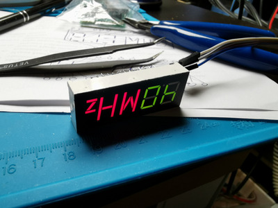
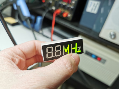
BTW speaking of these displays with "MHz" letters:

HanJammer wrote on 2020-12-04, 11:28:
^this and what we really need are those (attachments) as they are very rare and everything else is relatively easily sourced fro […]
Show full quote
Socket3 wrote on 2020-12-03, 15:13:

I'd be interested in purchasing several (4-5 units), but with a 3 digit display... I have several pentium 233 and k6-II/III PCs in AT cases with missing MHz displays....

^this
and what we really need are those (attachments) as they are very rare and everything else is relatively easily sourced from cases that are going to trash.

Good job on the display anyway.

This can be made, I did something similar (custom display) for flight simulator indicator lights. Level of complexity can vary - it depends if you want to just have all MHz letters light up at once, or do you need to have ability to light up particular segments? (is there any reason for this?)

A mask for the letters needs to be created. It can be a thin PCB with holes passing the light etched in copper. To get rid of copper color, it can be covered with theatrical ND gel adhered to it, or covered with black silkscreen.
Another way for making mask is to use laser-engraved piece of black-on-white ABS board.
OR (home-made version) it could be laser-printer with deep black (mixture of all colors + black on color printer) on tracing paper, then covered with clear tape.

Below that mask will be second PCB with small SMD LEDs of chosen color (or RGB... 😁 😁).
If we want to be able to light up particlar segments: the LEDs need to be precisely positioned in order to match the light mask. Then the LEDs will need to be separated from each other to prevent the light spill - a 3D printed "skeleton" with thin walls can be used for that.
If we just want to light up all MHz letters at once - one LED for each letter could probably suffice, a diffusing material (e.g. diffusion theatrical gel, or tracing paper) could be added to spread the light evenly.
In both cases, obviously a connector needs to be added.

Outer rectangular shell can be 3D printed. LED piece will be on the bottom, mask on the top and there can be hot glue or clear epoxy injected between them.

I would prefer to just make the "MHz" part and join it with already available digit displays. To make the seam invisible, you can just cover both pieces with ND gel, the display will appear to be almost black after that, but as soon as you turn it on, the letters and digits will appear (resistors need to be chosen properly so there will be enough power to make up for the light loss). OR an additional mask to cover the entire piece could be made.

OR it could be possible just to find alphanumeric LED displays, and use these. An additional mask could be printed to cover unwanted segments, or to make the seam invisible.

Repair/electronic stuff videos: https://www.youtube.com/c/adalbertfix
ISA Wi-fi + USB in T3200SXC: https://www.youtube.com/watch?v=WX30t3lYezs
GUI programming for Windows 3.11 (the easy way): https://www.youtube.com/watch?v=d6L272OApVg

Reply 69 of 112, by SETBLASTER

User metadata
Rank Member
Rank
Member
HanJammer wrote on 2020-12-04, 11:28:
^this […]
Show full quote
Socket3 wrote on 2020-12-03, 15:13:

I'd be interested in purchasing several (4-5 units), but with a 3 digit display... I have several pentium 233 and k6-II/III PCs in AT cases with missing MHz displays....

^this

and what we really need are those (attachments) as they are very rare and everything else is relatively easily sourced from cases that are going to trash.

Good job on the display anyway.

hi , where did you buy those leds with the red MHZ ? i have been looking for one of those for a long long time

Reply 70 of 112, by wiretap

User metadata
Rank Oldbie
Rank
Oldbie

Those have been out of production for the better part of 2 decades as far as I know. An alternative would be to use an alphanumeric style segmented display.

My Github
Circuit Board Repair Manuals

Reply 71 of 112, by wiretap

User metadata
Rank Oldbie
Rank
Oldbie

Assembled a board and got around to working on the code.. the numeric display works great with all digits (single and double digit). I just have to test the turbo LED and speed switch sensing.

Code attached.

fdg3CjCh.jpg

PrUV0cqh.jpg

z7mUhp0h.jpg

NPgsaMsh.jpg

4FW4e9Fh.jpg

Attachments

  • Filename
    program.c
    File size
    3.04 KiB
    Downloads
    138 downloads
    File comment
    Program Code
    File license
    CC-BY-4.0

My Github
Circuit Board Repair Manuals

Reply 73 of 112, by wiretap

User metadata
Rank Oldbie
Rank
Oldbie

Let me know some dimensions for a 3-digit. PCB size, digit size, and mounting hole locations. I only have one 3-digit to compare to, and it is in a weird case with other things like hdd/pwr LEDs integrated.

My Github
Circuit Board Repair Manuals

Reply 74 of 112, by wiretap

User metadata
Rank Oldbie
Rank
Oldbie

Ok, fully tested the this turbo display. It works great with MHz switching and turbo LED support!

Video:
https://youtu.be/Jka8PfParP4

My Github
Circuit Board Repair Manuals

Reply 75 of 112, by FAMICOMASTER

User metadata
Rank Member
Rank
Member

As the original case for my Turbo AT had a two digit unit which decided to let out the magic smoke, I would love to have one of these to replace it with. Would be nice to have a case that fits properly as opposed to the IBM 5170 case I've been using which doesn't seem to fit everything very well.

Reply 76 of 112, by wiretap

User metadata
Rank Oldbie
Rank
Oldbie

3-digit schematic thus far. Might have to change the 7-segment displays to something a different size. Not sure yet. I've been in and out of town the past few weeks, so I haven't had much time to work on this.

2CiBHdR.jpg

My Github
Circuit Board Repair Manuals

Reply 77 of 112, by Tiido

User metadata
Rank l33t
Rank
l33t

Would it make more sense to use an MCU with more IO so that you can forget the shift regs and mux the digits in the MCU itself ? It would do away with all the extra logic chips and maybe is even cheaper too. I think there's enough current handling capability that you don't even need to introduce transistors to drive the common anode/cathode of each digit.

Very nice work though ~

T-04YBSC, a new YMF71x based sound card & Official VOGONS thread about it
Newly made 4MB 60ns 30pin SIMMs ~
mida sa loed ? nagunii aru ei saa 😜

Reply 78 of 112, by wiretap

User metadata
Rank Oldbie
Rank
Oldbie

It's possible. There are probably 100 different designs that you could make for this project. I chose the ATTiny85 since it is very common (even during the chip shortages), it is simple to program, and it is easily replaceable/reprogrammable by a novice.

Feel free to design a MCU version and post it here. 😀

My Github
Circuit Board Repair Manuals

Reply 79 of 112, by Tiido

User metadata
Rank l33t
Rank
l33t

I was thinking like ATtiny24 but seems that it and its friends that have enough IO for direct driving displays are all out of stock in most places...
My todo list is too long to add one more thing into it (but I do have enterntained the idea of a turbo display, since I have lack of them for some cases I got).

Do you plan to make some for sale or should people make their own with the published materials ?

T-04YBSC, a new YMF71x based sound card & Official VOGONS thread about it
Newly made 4MB 60ns 30pin SIMMs ~
mida sa loed ? nagunii aru ei saa 😜