VOGONS


AMD K7 "goldfinger" cloning thread

Topic actions

Reply 180 of 256, by Doornkaat

User metadata
Rank l33t
Rank
l33t
snufkin wrote on 2021-04-06, 17:19:

Essentially, I think, this is something that may be a problem on paper, but in practice it could be that it's very rare that it's a problem. With the testing you'll be able to do on a range of motherboard that should give a good indication whether this is something to worry about. Could be worth bearing in mind if someone has a problem making a passive GFD work in the future.

Thank you for all the answers! 👍 You're right, many of my conclusions were based on additional assumptions so they're not necessarily valid.
To me the original device just worked and therefore in my logic any clone would too. I never understood how any of this worked until I got into this thread and obviously my understanding is still superficial. 😅
Mostly I'm glad that there is no reason to expect the passive design to cause any damage. I would have felt bad if I released a PCB that could cause damage to others' hardware. (Well, damage beyond what's to be expected in overclocking.)
If any incompatibilities (of course caused by the GFD) are found in my testing the worst case would be a setting not registering correctly. I can live with that. 😉
I'll keep testing and if others try the design on their boards I'll be happy to add their results to the post.

Cheers! 😀
Reply 181 of 256, by gex85

User metadata
Rank Member
Rank
Member

Wow, this has gained some traction once again. Great!
Since I have a few of the non-functional Northwind PCBs lying around (and one assembled), I might give your suggestions a try. But I currently don't have too much time to spare for retro activities, so it might take a few days.

But I have now calculated the cost for the Ninja Micro clones as I announced in this post: Re: Making an AMD "goldfinger" clone ?
I will be able to send out kits or assembled (and tested) units at 12,50€ each + shipping from Kiel, Germany. For assembled units, you are kindly requested to make a small donation as described in the post I linked above.
Since I will hand-solder everything, don't expect industrial-grade solder joints on the assembled units.
There are currently well over 10 kits left, so shoot me a PM if you want one.

My retro computers

Reply 182 of 256, by Mel427

User metadata
Rank Newbie
Rank
Newbie

Hi im Mel from Hanover, i would love to buy an assembled one from you. do you have a contact information? I can´t send an PM because i just registered new 😁

thanks 😀

486DX4 - Abit AH4T // Pentium II 333 - Voodoo2SLI // Athlon K7 Thunderbird 900@1Ghz- Geforce 4 4600Ti - Asus K7M //
Amiga 1200 - 68060 @ 66Mhz // Amiga 500 - Vampire 500 V2+

Reply 183 of 256, by ltsniper

User metadata
Rank Newbie
Rank
Newbie

Wow, fantastic work guys! I’ve been hitting up eBay regularly for the past few years trying to get my hands on a second hand GFD but they are as rare as hens teeth. I noticed a listing recently which stated it was a clone and that more info could be found here on Vogons so here I am. I’ve got a 500mhz and 550mhz Argon and a 850mhz Tbird (integrated L2), I’ve already opened up the Argon’s and replaced the thermal pads for the L2 and die. Can I please order 2 x unassembled PCB boards Gex85! (New user can’t PM) Lt. Sniper

Reply 184 of 256, by gbeirn

User metadata
Rank Member
Rank
Member

That's my listing. Welcome, stay awhile, it's pretty cool here.

I have sold 14 total across here and elsewhere. So if you are US based and interested, let me know. I don't think I will make another batch unless there is strong interest.

@Gex85 Attached is what you PM me about. I include that with my kits as well.

Attachments

Reply 185 of 256, by gex85

User metadata
Rank Member
Rank
Member
gbeirn wrote on 2021-04-08, 15:36:

That's my listing. Welcome, stay awhile, it's pretty cool here.

I have sold 14 total across here and elsewhere. So if you are US based and interested, let me know. I don't think I will make another batch unless there is strong interest.

@Gex85 Attached is what you PM me about. I include that with my kits as well.

Thanks a lot! In the meantime, I found that there's an executable on the Ninjamicros website on archive.org that contains the manual embedded in some sort of viewer executable. From there I printed it to PDF, please see the attached file.

Mel427 wrote on 2021-04-07, 17:53:

Hi im Mel from Hanover, i would love to buy an assembled one from you. do you have a contact information? I can´t send an PM because i just registered new 😁

thanks 😀

ltsniper wrote on 2021-04-08, 09:51:

Wow, fantastic work guys! I’ve been hitting up eBay regularly for the past few years trying to get my hands on a second hand GFD but they are as rare as hens teeth. I noticed a listing recently which stated it was a clone and that more info could be found here on Vogons so here I am. I’ve got a 500mhz and 550mhz Argon and a 850mhz Tbird (integrated L2), I’ve already opened up the Argon’s and replaced the thermal pads for the L2 and die. Can I please order 2 x unassembled PCB boards Gex85! (New user can’t PM) Lt. Sniper

Hi guys, I'm very busy lately, so sorry for the delay. I'll try to PM you both, don't know if you can reply, but I'll include an e-mail address.

Attachments

My retro computers

Reply 186 of 256, by gex85

User metadata
Rank Member
Rank
Member

For the Innovatek OC Card (the design used by Doornkaat), I looked up the documentation, too:

  • Website on archive.org (English): LINK
  • Website on archive.org (German): LINK
  • PDF Manual (German):
    Filename
    Innovatek OCDVr2 Manual German.pdf
    File size
    453.98 KiB
    Downloads
    87 downloads
    File comment
    OCDVr2 Manual (German)
    File license
    Fair use/fair dealing exception

My retro computers

Reply 187 of 256, by gex85

User metadata
Rank Member
Rank
Member

I have sent out the GFDs to everyone who ordered one on Thursday. Sorry for the delay again, my spare time is quite limited currently and soldering, testing, packing and posting took quite a while.
I currently have parts for 11 more GFDs that I am willing to sell, but if you need it assembled please expect it to take up to three weeks before I can ship. Unassembled kits can be sent out much faster. PM me if you want one 😀

My retro computers

Reply 188 of 256, by Xplo

User metadata
Rank Newbie
Rank
Newbie

What an awesome thread and thank you to everybody who participated to make this possible

Having read the thread it has got quite confusing which forum members have designed which type of GFD clone, and which colour pcb etc

Maybe we could get a collective post together with all this information and photos in one post which can be kept updated?

Reply 189 of 256, by wiretap

User metadata
Rank Oldbie
Rank
Oldbie
Xplo wrote on 2021-04-24, 14:13:

What an awesome thread and thank you to everybody who participated to make this possible

Having read the thread it has got quite confusing which forum members have designed which type of GFD clone, and which colour pcb etc

Maybe we could get a collective post together with all this information and photos in one post which can be kept updated?

This is the main one I cloned which is proven working by numerous people.

Re: Making an AMD "goldfinger" clone ?

My Github
Circuit Board Repair Manuals

Reply 190 of 256, by Deksor

User metadata
Rank l33t
Rank
l33t

Do you want me to update the first post to make things clearer ? What would you like on the first page ?

Trying to identify old hardware ? Visit The retro web - Project's thread The Retro Web project - a stason.org/TH99 alternative

Reply 191 of 256, by Xplo

User metadata
Rank Newbie
Rank
Newbie
Deksor wrote on 2021-04-24, 14:29:

Do you want me to update the first post to make things clearer ? What would you like on the first page ?

That would be amazing. I think in the same format as wiretaps post would be greatly helpful to all prospectives followers with all the info combined

Reply 192 of 256, by Xplo

User metadata
Rank Newbie
Rank
Newbie
wiretap wrote on 2021-04-24, 14:27:
Xplo wrote on 2021-04-24, 14:13:

What an awesome thread and thank you to everybody who participated to make this possible

Having read the thread it has got quite confusing which forum members have designed which type of GFD clone, and which colour pcb etc

Maybe we could get a collective post together with all this information and photos in one post which can be kept updated?

This is the main one I cloned which is proven working by numerous people.

Re: Making an AMD "goldfinger" clone ?

Awesome. Thanks. Are there any remaining?

Reply 193 of 256, by wiretap

User metadata
Rank Oldbie
Rank
Oldbie

Not sure if anyone have any pre-built left. All I have left are a few unpopulated PCB's. However it would probably be cheaper to order them from JLCPCB since a set of 5 is like $7 shipped.

My Github
Circuit Board Repair Manuals

Reply 195 of 256, by Doornkaat

User metadata
Rank l33t
Rank
l33t

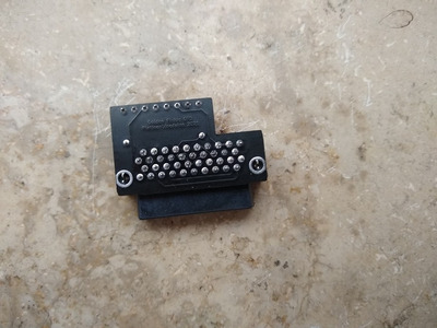
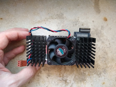
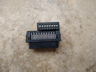
Since it appears there is still some degree of interest in the passive devices here's what the final revision of my size reduced Innovatek clone looks like:

IMG_20210425_095951989.jpg
Filename
IMG_20210425_095951989.jpg
File size
116.4 KiB
Views
1372 views
File license
Fair use/fair dealing exception
IMG_20210425_095958568.jpg
Filename
IMG_20210425_095958568.jpg
File size
113.9 KiB
Views
1372 views
File license
Fair use/fair dealing exception

The size is about as small as it gets and the use of the tri state switches prohibits settings that would result in a short so I think it doesn't get much better than this as far as passive GFDs go.
This post lists the motherboards I have tested it on so far.
I don't know if anyone else ordered the PCBs and assembled/tested one. If you did please let me know what motherboard and CPU you have tried it on and how it went. 👍

Last edited by Doornkaat on 2021-04-25, 08:27. Edited 2 times in total.

Reply 196 of 256, by Doornkaat

User metadata
Rank l33t
Rank
l33t

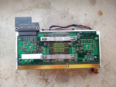
Mounted on CPU:

IMG_20210423_172037259.jpg
Filename
IMG_20210423_172037259.jpg
File size
213.15 KiB
Views
1372 views
File license
Fair use/fair dealing exception
IMG_20210423_172143011.jpg
Filename
IMG_20210423_172143011.jpg
File size
315.58 KiB
Views
1372 views
File license
Fair use/fair dealing exception

Reply 197 of 256, by snufkin

User metadata
Rank Oldbie
Rank
Oldbie

Cute. The only thing I can think that would make it better would be if there were a straight-through (rather than right-angle) version of the main connector. Or a right-angle mounted dip switch. That would let you have the switches facing upward to slightly improve accessibility.

Or... Clip off all the unused pins on the connector. I think the minimum remaining would be 14 out of the 40. That would clear a lot of space on the back of the PCB and might let the dip switch partially overlap the footprint of the main connector.

Reply 198 of 256, by Doornkaat

User metadata
Rank l33t
Rank
l33t
snufkin wrote on 2021-04-25, 10:32:

Cute. The only thing I can think that would make it better would be if there were a straight-through (rather than right-angle) version of the main connector. Or a right-angle mounted dip switch. That would let you have the switches facing upward to slightly improve accessibility.

I'm not too sure either of those parts exist. I had thought about using a right angle switch too but it seems nobody makes those.

Or... Clip off all the unused pins on the connector. I think the minimum remaining would be 14 out of the 40. That would clear a lot of space on the back of the PCB and might let the dip switch partially overlap the footprint of the main connector.

I had considered a similar approach and while that would work in theory (You could use holes 21+37 on the AMP connector footprint to put pins 9+10 of the switch through if you removed the corresponding pins on the AMP connector. This would only leave pins 1-8 hanging over the AMP connector and shrink the PCB roughly another 6-7mm.) you would have to either shorten the pins on both about 1.2mm so they don't collide or mount the switch elevated. Also the switches would have to be soldered from the component side which is possible but... unorthodox. 😉 All in all I don't think it's worth it to route the traces around the holes for the AMP connector and to complicate assembly by having to modify the parts.
If you think it's worth your while I posted the schematics in this thread so feel free to alter the design however you please. (And also to post your design here. 😀 )

Reply 199 of 256, by snufkin

User metadata
Rank Oldbie
Rank
Oldbie
Doornkaat wrote on 2021-04-25, 12:14:

If you think it's worth your while I posted the schematics in this thread so feel free to alter the design however you please. (And also to post your design here. 😀 )

Ah, this is firmly in to diminishing returns territory for the possible space savings. Yours is probably as far as is sensible.

Although...
Straight connector (I think): https://www.digikey.co.uk/product-detail/en/t … 01-4-ND/1864025
Surface mount dip switch: https://uk.farnell.com/alcoswitch-te-connecti … -smd/dp/2792786

Now, me, I was sketching out a plan to go the other extreme. Couple of 16 position rotary switches, low voltage micro-processor, charge pump to get ~3V from Vcore, some shift registers for the 12 outputs. Could then just dial the Vcore and frequency up and down, and avoids any possible voltage level issue. Attach a thermometer to the uP and could maybe start to implement thermal throttling/frequency boost (do we know if the athlon only reads FID at boot?). I'm sure there're more ways to make it needlessly complicated (bluetooth with control app on phone?). All for something that probably gets set once... So I managed to stop doing that.