I've tried contacting PCPartner to see if they still have the BIOS (since they still offer downloads for their Socket 7 motherboards), but alas. Props to them for responding very quickly to my question though.
Deunan wrote on 2020-01-29, 22:18:
I had two 486 mobos that didn't POST or beep when there was something wrong with the RAM sticks. So having a PC speaker working is not exactly a great help in diagnosing issues. A POST card will serve you much better.
Since you have a scope, probe the ISA slot signals - reset, clocks, address/data lines for any indication of activity. Or the BIOS chip /CE and /OE lines. Could be the CPU is dead or somehow not configured properly.
The CPU does work in another board. It's a AMD 5x86 and the board I'm trying to revive is newer than the other one, so I think it should support it.
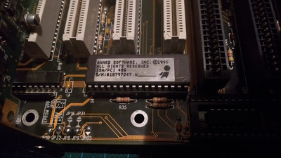
There is a question of the jumper settings: the manual that can be found online for the M486-UPI is missing some pages in the CPU jumper settings chapter. I'm using the one for the Enhanced AMD 486 DX4 now (with a System Clock Speed of 33MHz) but there might be a specific setting for 5x86 on the missing pages.
I ordered a POST BIOS card from China last week but who knows how long it will take to arrive, so I will try to measure the lines you mentioned. What kind of signals should I be seeing?
Horun wrote on 2020-01-30, 02:16:
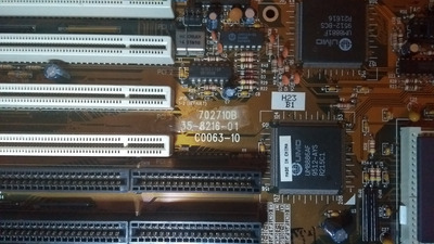
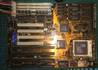
Can you take a good picture of the whole board and post it ? Many times a board was used in a few different computers and someone here may have that same board like from Leading Technology, Laser (all Vtech brands) or some other brand. The manual is good for jumpers but bad for identifying specifics...
Yes, I will take one tonight. There is a good chance it came from a Laser machine since those were heavily advertised here in the 90s.
SquallStrife wrote on 2020-01-30, 02:18:Probing the Speaker header with an oscilloscope has a couple of gotchas. […]
Show full quote
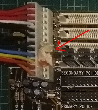
Probing the Speaker header with an oscilloscope has a couple of gotchas.
First, the data pin is open collector, so it's either in a high-impedance state, or pulled low with a transistor. You will not see a signal on it with an oscilloscope unless you bias it up with a resistor.
The speaker's impedance is 8ohm, so a 10ohm resistor should suffice.

You can bias it using the speaker itself, but back EMF from the speaker will distort the waveform.
Second, the power supply inside a desktop PC is referenced to mains earth, and so are your scope probes. If you you attach probe ground to any voltage rail (in the case you want to reference your readings to, say, +5v, as would be the case if you simply connected the probe across the speaker terminals), you are effectively shorting that rail to ground, and will at best trip the overcurrent protection in the PSU, at worst melt your wires and/or start a fire.
For some reason I have trouble grasping grounding (I'm very new to electronics). I don't have the board in a case at the moment, so can I attach the probe to one of the screw holes in the corners of the board instead?
I have a bunch of resistors so I'm sure I have a 10ohm one, so I will try it tonight as well.
Am486 DX4 120MHz, no L2, 16MB, Tseng ET4000/W32 1MB VLB, ESS ES1869 /// 5x86 133MHz, 256kb L2, 64MB, S3 Virge/DX 4MB PCI, SB16 + Yucatan FX, PicoGUS /// Pentium III 1GHz, 512MB, Asus V7700 64MB AGP, SB Live!