VOGONS


First post, by evildave9000

User metadata
Rank Newbie
Rank
Newbie

Hi everyone.

I've recently got back interested in vintage computers of my youth and have decided to try to build a working 486. I've purchased a motherboard, CPU (x2), video card, PSU, RAM, keyboard, sound card, and hard disk controller. I've not been able to find a suitable case yet.
So, I haven't worked on an AT machine for probably 20 years or more and I'm a bit rusty.

The specs are:
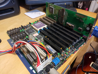
Motherboard: Pine PT-430, 256k cache, 3x VLB, 3x 16-bit ISA, 1x 8-bit ISA
RAM: 2x 8mb 72 Pin SIMMs
CPU: It's ST 486 DX2-80 5v (also bought an Intel DX4 100, but realised it wouldn't work on this motherboard without a daughterboard voltage regulator, which I may attempt to build at some point)
Graphics: S3 Trio32 2mb
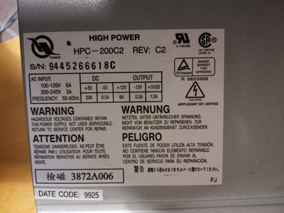
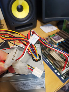
PSU: Hi Power HPC-200C2 200w

So I thought I would attempt to get it to at least power on and go from there, but I haven't been able to get anything from it. All I have attached to the board is the graphics card, RAM, CPU, a keyboard and of course the PSU. The power supply doesn't have an on/off switch and I'm thinking this may be the problem? Is the PSU too new for the motherboard and it is expecting the on/off signal from the motherboard? From the little documentation I've found for the motherboard, there is no mention of a power switch connection on the motherboard, so I guess the motherboard is expecting a PSU that is either on or off?

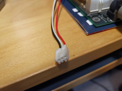
Using a multimeter, I've determined that there is no power going to motherboard at all (although the battery appears to work!). The only thing getting power, at 5v, is the 3 pin connector pictured - is this for a power switch? Or for a fan or something else?

Attachments

Reply 1 of 35, by LewisRaz

User metadata
Rank Member
Rank
Member

AT psu doesnt get its on signal from the motherboard. perhaps that connector is for some sort of relay that allows a button to turn it on instead of a switch?

My retro pc youtube channel
Twitter

Reply 2 of 35, by evildave9000

User metadata
Rank Newbie
Rank
Newbie

That's what I was thinking. The PSU does nothing when I plug it in, either hooked up to the motherboard or not. The connector has three wires: Red 5v, Yellow 5v and Black GND. I've read that some PSUs won't power on without sufficient load, so maybe I should hook up a HDD to one of the Molexs?

Reply 3 of 35, by CoffeeOne

User metadata
Rank Oldbie
Rank
Oldbie
evildave9000 wrote on 2020-03-12, 19:40:

..... The power supply doesn't have an on/off switch and I'm thinking this may be the problem? Is the PSU too new for the motherboard and it is expecting the on/off signal from the motherboard? From the little documentation I've found for the motherboard, there is no mention of a power switch connection on the motherboard, so I guess the motherboard is expecting a PSU that is either on or off?
.....

WTF.
I guess you bought a proprietary power supply.
Real AT power supplies have +5V, +12V, -12V, -5V and a primary power switch.
They DO NOT have a 5V SB line, as there is no stand by.
So buy another 😀

Reply 4 of 35, by LewisRaz

User metadata
Rank Member
Rank
Member

There also appears to be an extremely bent pin on the external battery connector(Judging by its location) JP1
Can also see a few areas of rust. Have you checked the board for any damaged traces? This wont be why its not powering but could be issues once it does get power.

My retro pc youtube channel
Twitter

Reply 5 of 35, by quicknick

User metadata
Rank Oldbie
Rank
Oldbie

This kind of PSU has been discussed over here recently, but I don't remember what thread. On the 3-pin connector you have GND, +5Vsb and the equivalent of PS_ON# from ATX supplies, that you must connect to GND for the PSU to start. Take care not to connect the +5Vsb to ground, though 😀

Reply 6 of 35, by evildave9000

User metadata
Rank Newbie
Rank
Newbie

CoffeeOne - Damn... It was very cheap at least!

LewisRaz - There is some rust on the 30pin Simm clips, but weirdly not on the 72pin clips. A spot of rust in the KBD controller chip seating, but this isn't being used. I had noticed the bent pin, but I hadn't planned on using this and I think it will bend back with some pliers. Apart from that the board looks in pretty good nick.

quicknick - Ok, so if I short one of the 5v lines to GND from that connector, it should turn on? How do I know if it is the red or the white?

Thank for your replies everyone

Reply 7 of 35, by CoffeeOne

User metadata
Rank Oldbie
Rank
Oldbie
evildave9000 wrote on 2020-03-12, 20:33:
CoffeeOne - Damn... It was very cheap at least! […]
Show full quote

CoffeeOne - Damn... It was very cheap at least!

LewisRaz - There is some rust on the 30pin Simm clips, but weirdly not on the 72pin clips. A spot of rust in the KBD controller chip seating, but this isn't being used. I had noticed the bent pin, but I hadn't planned on using this and I think it will bend back with some pliers. Apart from that the board looks in pretty good nick.

quicknick - Ok, so if I short one of the 5v lines to GND from that connector, it should turn on? How do I know if it is the red or the white?

Thank for your replies everyone

Maybe you can make a useful photo, where we can see all the cables that come out of the power supply?

EDIT: You made it, like you would have to hide something 😁

More EDIT:
If quicknick is right, the close the white and the black wire. red is 99.999% => 5 volts.
And sorry for my wrong wording before, there is not really a 5VSB line. The 5VSB means the the power supply will provide up to 1A (equals to 5 Watts) when it is turned off.

Reply 8 of 35, by quicknick

User metadata
Rank Oldbie
Rank
Oldbie

You can open up the PSU and find the points where those wires are attached, they are usually labeled on the PCB. (Not really recommended if you have no experience with power supplies. Absolutely disconnect it from mains if you do that).
There are other means. Instead of a short you can use a resistor of around 22 ohm. PSU should start with that between GND and PS_ON, but resistor will start smoking if connected to GND and +5Vsb.
Or if you have a 5 volt load (can't think of any; flashlight bulb maybe?), you could use that.
Intuition tells me the +5Vsb is the red wire.

Reply 9 of 35, by evildave9000

User metadata
Rank Newbie
Rank
Newbie

Both the red and the white show about 5v on the multimeter. I'm not sure I want to go opening up the PSU just yet and I don't really know what I'm doing in there.

So your thinking is that 3 pin connector is for a specific case that would have a standby button and power button, that would switch between OFF, ON (we assume White + GND) and Standby (we assume Red + GND)???

Or am I misunderstanding the purpose of the +5VSB?

Attachments

Reply 10 of 35, by quicknick

User metadata
Rank Oldbie
Rank
Oldbie

No, the 3-pin connector goes to the motherboard, and also on the motherboard there is a 2-pin header that goes to the front panel power switch. Think of an ATX but with non-standard wiring/plug. There was an older discussion about some IBM using this system, and much more recently about something similar but from another brand.

Found the older one, it is here.
Take care, the solution in the last post is for using the non-standard board with a standard PSU, you need to do the other way around 😀

Reply 11 of 35, by CoffeeOne

User metadata
Rank Oldbie
Rank
Oldbie

Sorry to say, but we still do not see all cables that come out of the power supply?
Or do we?
So there are the 2 for the AT mainboard, 2 power connectors for hard drives, and one for a floppy.
+ the mystery red, white, black.
Nothing else?

Reply 13 of 35, by quicknick

User metadata
Rank Oldbie
Rank
Oldbie

The PSU is from a branded system, for sure. It probably has only the connectors that were needed in that system.

Edit: after a quick search, it seems the PSU for the AcerPower 4100.

Last edited by quicknick on 2020-03-12, 21:11. Edited 1 time in total.

Reply 14 of 35, by CoffeeOne

User metadata
Rank Oldbie
Rank
Oldbie
evildave9000 wrote on 2020-03-12, 21:04:

Correct, that's all the cables

Hmm, that's really a crap power supply, so you can have only 2 harddisks or one harddisk and a CD ROM without additional adapters.
OK, nevermind, you wrote both the red and the white show 5V against ground.
Normally red is 5V and white is -5V at AT power supplies. Do you measure 10 volts between red and white?

Reply 15 of 35, by quicknick

User metadata
Rank Oldbie
Rank
Oldbie

In this case, the white wire on this small 3-pin connector is probably the PS_ON, pulled high internally. The wire is green in the ATX standard, but it works the same. You can measure (close to) 5 volts on the PS_ON# when connected to mains but the PC turned off, that's how the PSU "knows" when to turn on: when the motherboard pulls this pin to GND...

Edited: less confusing, I hope 😀

Last edited by quicknick on 2020-03-12, 21:40. Edited 1 time in total.

Reply 16 of 35, by CoffeeOne

User metadata
Rank Oldbie
Rank
Oldbie
quicknick wrote on 2020-03-12, 21:14:

The white is probably the PS_ON, pulled high internally. Same as the ATX stardard. You can measure (close to) 5 volts on the PS_ON, that's how the PSU "knows" when to turn on: when the motherboard pulls this pin to GND...

Nope. Green is power on @ ATX power supplies.

Reply 17 of 35, by quicknick

User metadata
Rank Oldbie
Rank
Oldbie

Good luck finding the green wire on the PSU that's the subject of this thread. Since it's not a "true ATX", why assume it uses the same colour code for the wires? Why would -5V be present on the small 3-pin connector, and how would you power up this PSU if it would lack some sort of PS_ON signal?

Edit: I see where the confusion comes from. I was referring to the PS_ON# line being pulled up internally, like it's on the ATX, not that it's white on ATX. Will rephrase the previous post.
White on ATX is -5V indeed, and it's only present on the oldest of ATX supplies (before ATX 2.0 or 2.1 I think)

Reply 18 of 35, by CoffeeOne

User metadata
Rank Oldbie
Rank
Oldbie
quicknick wrote on 2020-03-12, 21:30:

Good luck finding the green wire on the PSU that's the subject of this thread. Since it's not a "true ATX", why assume it uses the same colour code for the wires? Why would -5V be present on the small 3-pin connector, and how would you power up this PSU if it would lack some sort of PS_ON signal?

Edit: I see where the confusion comes from. I was referring to the PS_ON# line being pulled up internally, like it's on the ATX, not that it's white on ATX. Will rephrase the previous post.
White on ATX is -5V indeed, and it's only present on the oldest of ATX supplies (before ATX 2.0 or 2.1 I think)

Yeah, but it would be really weird to use the same colour white on 2 different wires for completely different things. But maybe they did ....

Reply 19 of 35, by Horun

User metadata
Rank l33t++
Rank
l33t++
quicknick wrote on 2020-03-12, 21:06:

The PSU is from a branded system, for sure. It probably has only the connectors that were needed in that system.

Edit: after a quick search, it seems the PSU for the AcerPower 4100.

I was thinking something like a Zenith or DEC system. The dual P5 in this thread NEC Proserva V Plus (dual socket 7 system) (have a lead on multiple of these)
has a similar (but differant) special PSU lead to the board, then the board header has Power switch, reset and LEDS connections to front panel.
Finding the proper PS-On wire using a 22ohm resistor is a good idea. Being a 486 board 200watt PSU is more than enough...

Hate posting a reply and then have to edit it because it made no sense 😁 First computer was an IBM 3270 workstation with CGA monitor. Stuff: https://archive.org/details/@horun