VOGONS


Reply 40 of 176, by Vipersan

User metadata
Rank Oldbie
Rank
Oldbie

Calling it a night ..I'm knackered..
But at least I can call today a success.
Finally got DOS 6.22 installed on the Conner.
I thought about it logically for some time and concluded that if I could install DOS 5 with the GW-Gear Bios...then there was no reason I couldn't get 6.22 in there ..so Found some unused floppies and downloaded a version of 6.22 from a different source ..wrote a new set of floppies.
reformatted the conner and tried yet again ..and this time the install concluded..
It took what seemed forever but eventually got remove floppy disk and press enter for reboot ..
Well it booted ...and there was my C prompt.
I also ordered 4 x 30 pin SIMM slots from RS just in case the SIPPS dont work..
apparently the SIPP bases are a straight pin for pin swap with 30 pin SIMMs ...this would give me more options but they will only be fitted IF the SIPPS refuse to play nice.
Others have had issues so I want to be prepared...particularly as they were so cheap at RS ..
£9 for 4 delivered...and I know they will get used on another project if not this one.
Tomorrow I'll install Checkit and Possibly Xtree gold.
..but my old eyes are closing and it's time I got some sleep.
rgds
VS

Reply 41 of 176, by Vipersan

User metadata
Rank Oldbie
Rank
Oldbie
DSCF0047.JPG
Filename
DSCF0047.JPG
File size
217.23 KiB
Views
1036 views
File license
Public domain

Popped Checkit on the C: drive for convenience ..
Dug out a 80207 Math co..and fitted that.
and it was recognised by checkit.
I'd say today is off to a good start.

Reply 42 of 176, by Vipersan

User metadata
Rank Oldbie
Rank
Oldbie

Moved to a more modern flat screen display with more screen real estate ..
My old eyes are paying a heavy price atm.
Ran Checkit from the Conner.
Of particular interest to me was how the old Conner performed..
I'd say excellent for such an old beast.
So ..I guess it's very much down to a memory upgrade now as most everything else is up and running..
No doubt that will be a challenge when the SIPPs arrive.
Other things to do now are ..sort out a serial mouse for it..and try and find a suitable sound card.
Question ...were simple 8 bit stand alone ISA cards made for adding PS2 mice ?
rgds
VS

Attachments

  • DSCF0052.JPG
    Filename
    DSCF0052.JPG
    File size
    240.04 KiB
    Views
    1032 views
    File license
    Public domain

Reply 43 of 176, by Vipersan

User metadata
Rank Oldbie
Rank
Oldbie

Ok ..Time to ask for help again..
Finally found what I was looking for in my stash..
An ESS MF-1115 Audio Drive ES688 jumpered ISA card.
I am no expert by any means when it comes to installing sound cards in DOS PCs ...particularly one this old.
I am therefore relying on some kind expert to lead be through the process since I have no driver or application software.
TBH I dont even know if it works but has been stored safely in an anti static bag so I'm hopeful.
The inevitable questions follow...
How suitable is this card for a 286 ?
How easy is it to install ?
What drivers/software will I need ? etc etc etc
rgds
VS

Reply 44 of 176, by Vynix

User metadata
Rank Oldbie
Rank
Oldbie

It should be a matter of popping it in (though you may have to do some tweaking, myself I don't remember very well what you need to do with the jumpers), then install the drivers...

Which can be found here: http://vogonsdrivers.com/getfile.php?fileid=372&menustate=0

Proud owner of a Shuttle HOT-555A 430VX motherboard and two wonderful retro laptops, namely a Compaq Armada 1700 [nonfunctional] and a HP Omnibook XE3-GC [fully working :p]

Reply 45 of 176, by kool kitty89

User metadata
Rank Member
Rank
Member

It might be easier to install DOS on a drive using another machine (or just another motherboard on a testbench/box/wooden board/etc) and then plug the drive back into the machine.

So long as the BIOS is compatible with the disk geometry (or fake/translated geometry) itself and the file system is 286 compatible, it should work OK.

I had a DOS 6.21 install that was left over on an old/junk drive I got a while back that seemed to have no problems on booting on various boards I've been testing, or at least all the AMI BIOS based ones. (the oldest of those are 1989 or 1990 BIOS revisions for D60 boards) Those are both single-chip BIOS ROM boards.

There's an older ACT based 286 board that also worked for a while, but is currently non-functional and worked OK with an AMI BIOS from another (non-working) ACT board but not the Quadtel BIOS it came with, and I can't play around with that more unless I get it working again.

The CHIPS based Biostar board you have seems closer to the D60 boards in age and feature set anyway and more competitive with the Headland H12 if there's a zero wait state option. (and the 80 ns printing on some revisions of this same board points to zero wait state support ... or at least 80 ns is excessive for 12 MHz operation) And it integrates the DMA controllers like the H12, which the D60 does not, but also integrates the CMOS RAM and realtime clock logic, which I don't think the H12 does. (the D60 does not, though some boards, like the M209, use a C&T ASIC instead of individual DMA and clock/CMOS chips)

I found documentation for the chipset itself, and it supports zero wait state mode and was specified for up to 12.5 MHz (at least officially).

https://www.datasheetarchive.com/f82c235-datasheet.html

It's LIM EMS 4.0 compatible, which technically means it should support up to 32 MB, but that requires the board to actually route address lines accordingly, not that much of anything 286 compatible could use that much RAM (particularly in DOS), but it's kind of neat to have EMS provisions well beyond the 286's own protected mode constraint. (and if the necessary address lines are actually present on the SIPP sockets, or at least any easily-solderable pins on the board, an expansion module would work; but connecting directly to the chipset address lines would be a lot more risky and fiddly with those tiny pins on the QFP mount ... not really worth it even for some exotic hardware hacker back in the early 90s)

More realistically, I wonder if any (or maybe even most) of these SIPP and SIMM based boards do support the full 16 MB 24-bit address space, even though most documentation only specifies 4 MB max. (and some boards have jumper setting for different banks, but not all of those actually require the right jumper settings to function, or will work with all the jumpers left open as my Hedaka board seems to: it also doesn't seem to allow jumper-select to switch to the DIP RAM while SIPPs are installed, which would be nice for testing purposes, since I have 60 ns DIPs and that board actually takes 2 MB in DIP sockets as well as 4MB in SIPPs)

I was also wrong about my D60 boards. They can lose the disk drive parameters under some conditions, but I'm just not sure what. I do know for a fact that the M205 retained the full C/H/S parameters correctly after sitting in a box for approximately 8 years with no battery, so the CMOS RAM or whatever it is must use very very little power and stay valid with very low voltage from residual capacitor charge. (it's definitely not on a shared circuit with the realtime clock logic, since the date/time dies almost immediately with no battery power; and given the RTC chip/logic should use a lot more power than a tiny block of CMOS static RAM or a similar bank of dedicated registers/scratchpad RAM somewhere in the chipset, that makes the situation more plausible)

Oh and there's at least one other user on vogons who's been messing around with that MB-1212C motherboard:
Biostar MB-1212C (SIPP version) extended memory problem.

For what that's worth.

Reply 46 of 176, by Vipersan

User metadata
Rank Oldbie
Rank
Oldbie

Thanks for the extra info K K ..
I am aware of that thread ...as it's where I found links to the GW Gear bios I'm currently using..
There are no jumpers on my mobo relating to the sipps sockets ..or at least none that Ive found.
So wondering now if the 1mb 4x256 SIPPS I have on order will even be recognised or configurable.
Only time will tell.
Certainly it seems that this single bios C & T mobo is at best very limited and certainly wasn't designed for use with large hard drives.
No doubt I'll be back again soon with more questions than answers.
rgds
VS

Reply 47 of 176, by kool kitty89

User metadata
Rank Member
Rank
Member

I forgot to mention it before, but I noticed Stason (and arvutimuuseum) seem to mix up Citygate and C&T in some instances, though not relevant to your Biostar board.

The ILION M-205 (also PCChips and Triple D, probably other branding) gets listed as C&T, but I don't think fake CHiPS & Technologies branding/stickers were ever used on those, so it seems like a straight error on confusing the CG logo with C&T.

The M-209 gets listed as PC Chips and the Hedaka 988 gets listed as Hedaka, too, but that's due to stickers (for Hedaka at least) and either remarking or (more likely by the looks of it) OEM-specific vendor printing. (ie PC Chips wanting their name on it rather than the CG marking, even though the actual part numbering remains the same)

Some M205 variations have PC Chips branded printing and some M209s have plain CG marked chips too, but the only relation to C&T would be that DMA/CMOS companion ASIC on the 209 (not relevant to the 205 at all) and some of those have Siemens markings instead. (licensed/outsourced production or pin-compatible clone/competitor, not sure)

Reply 48 of 176, by Vipersan

User metadata
Rank Oldbie
Rank
Oldbie

Well ..the 4 x 256 SIPPS arrived ..and were fitted..
The PC still booted but the extra ram was not seen or added.
Suspecting that the sipp slots were mapped into the same location as the DIP chips ..I pulled all the DIPS out of their sockets ..and rebooted ..
Exactly the same RAM available at boot which to me confirms this theory.
There are no jumpers on the mobo ..so it doesn't look like the sipps can be added as extra memory.
I guess it is either/or.
My next idea is to obtain 4x 1mb 30 pin simms ..and pop these in to the SIMM bases I got from RS.
Theoretically these can then be plugged directly into the sipp bases (also 30 pin).
And hopefully I will end up with 4mb total.
Its a gamble but worth a shot..

Reply 49 of 176, by kool kitty89

User metadata
Rank Member
Rank
Member

It seems like most motherboards with DIP sockets and SIPP or SIMM sockets will only use one or the other at a time, not both. They usually have jumpers to select which bank(s) to use, but those aren't always necessary to use or don't even seem to do much of anything in some cases.

My Hedaka 988 doesn't seem to be have any differently with any of the RAM config jumpers set (assuming Stason is correct about those being DRAM select jumpers). I know it ignores one or the other with both installed, but I forget which it defaults to. (it would make sense to default to SIPPs so users with the small bank of DIP RAM pre-installed could upgrade without having to pull them)

https://stason.org/TULARC/pc/motherboards/M/M … 6-KP-286HF.html

This board (and probably the similar/identical KP-286M) is the first of these 286 boards I've seen to explicitly support all onboard RAM banks and types at once.

It doesn't appear to have DRAM selection jumpers, but looks like it requires the DIP RAM to be installed first, then successive banks of SIMMs up to 5 MB (though may support more than that). So I assume the 1MB of DIP RAM is mapped to the base memory area and maybe to the full base 1 MB address space, and memory above that is available as XMS or EMS.

It'd be nice if the UMA was useable, as a lot of 286 boards avoid that address range and remap that 386 kB to EMS or XMS or shadow RAM. (or allow selection in the BIOS: the D60 does EMS or Shadow RAM, the ACT chipset EAT-12 I have does XMS, though that board seems to have stopped working for now)

Since EMS usually uses a chunk of the UMA, it'd be interesting if remaining UMBs were still accessible with EMS enabled. (granted it's nice to allow the whole 384kB to be used as EMS with no wasted memory holes)

I could of course be assuming wrong, and this Suntac board just works like more typical ones with the UMA limited to normal I/O, BIOS, video, etc addresses and not system RAM. (and the EMS page frame)

If you're looking to use faster RAM and have slower 1MB SIPP modules available, there's always soldering in new RAM, and 60 ns 256x4-bit Siemens DRAM chips seem pretty plentiful and affordable from some chinese sellers. (and have been for at least the last 6 months)

I've tried these from a couple different sellers and the mix of chips I got seemed about the same and none appeared to be faked/remarked and have worked so far up to 27 MHz in my M205. (though all arrived as pairs loose in little plastic zip-lock dime bag type deals which were then packaged inside gray plastic mailing bag/package/pouches, no anti-static material and no ... pro-static foam used on them either; a few minor bent pins, but nothing problematic)

They also run totally cool to the touch, unlike some other CMOS chips of that density that run quite warm, even some 60 ns stuff. (and merit heatspreaders or cooling fans to max out their timing in overclocked systems)

I think these are much newer/later production chips and they're either new old stock or really clean socket pulls given the condition of the tinning on the pins. (the un-bent examples also seemed to have pin angle close to factory spec too, but sometimes resellers reset the pins too, but I've also done my own pulls that can retain that angle and make it near impossible to re-install them without straightening the pins first: ie the pins remained very springy while installed in whatever board they were in and/or had sockets that kept the pins pushed outward while installed and ended up conformed to that shape)

You could also solder on DIP sockets to the SIPPs, so you can swap out DIPs as needed. (for use in other projects or to swap/test bad DIP chips)

Since you've got the small bank of DIP sockets already, you can pretty well test any DIPs in there anyway, so no headache of soldering in unknown-good/bad DIPs and finding the SIPP non-working, but the flexibility of sockets would be nice.

Hmm, plus with SIPPs rather than SIMMs, the added bulk/thickness of sockets wouldn't prevent installation, just needing to fiddle with bending the SIPP pins a bit to angle the modules apart. (some SIMM socket spacing would allow enough space too, but others may not)

Granted lots of soldering work involved in desoldering and repopulating the SIPPs.

There's also cutting and rerouting address lines on the board, but that seems like even more trouble with a lot more room for damaging the board.

Reply 50 of 176, by Vipersan

User metadata
Rank Oldbie
Rank
Oldbie

Thanks KK .
As usual ..a very informative post ..
I shall of course be updating my progress as I go ..
with photos when needed.
I'm eager to test with 4mb (4 x 1mb simm) in simm sockets plugged directly into the on board sipp socket ...
but will have to wait till the 4mb of matched 70ns simms I ordered arrive.
towards weekend I suspect.

I'm impatient by nature ..and like to keep busy .
But under lockdown atm ..so really have no choice do I ?

Stay safe everybody.
rgds
VS

Last edited by Vipersan on 2020-04-01, 08:39. Edited 1 time in total.

Reply 51 of 176, by Vipersan

User metadata
Rank Oldbie
Rank
Oldbie

So it looks like I have limited control over dram expansion of this mobo ..
Banks 0 and 1 are occupied by the DIP sockets.
Banks 2 and 3 are the SIPPS.
Any configuration requiring 1mb or higher does indeed require removal of the DIP chips ..and fitting of SIPPS..
Full expansion to the max of 4mb ..does indeed require pulling the DIPS and fully populating the SIPPS with 4 x 1mb.
I'd sort of figured this out myself ..but this image from Arvutimuuseum sort of confirms it.
My only worry now is replacing those SIPPS with 70 ns SIMMS ..but fingers crossed this will have the required result ..when they arrive.
rgds
VS

Attachments

  • DRAM.jpg
    Filename
    DRAM.jpg
    File size
    78.56 KiB
    Views
    919 views
    File license
    Public domain

Reply 52 of 176, by Vipersan

User metadata
Rank Oldbie
Rank
Oldbie

Oh boy ..
got lucky withis one ..
The seller of the princeton (4x 1mb 9 chip simms only lived a few miles from me ...so popped them in an envelope with note saying he/she was hand delivering them.
So I never met the seller ..but the simms landed on my mat about an hour ago.
Wasting no time I fitted them in those 4 simm slots from RS ..and simply pushed the pins into the Sipp bases ...making sure to get the orientation correct ..
Well the photos attached say it all.
I now have 4mb ..and the extended memory looks good.
slight correction though ..
I previously said 70 ns ..they are in fact 80 ns.
The DIP chips go into my swag &..
The project moves forward >>>>>>>>>>>>>>

Attachments

  • DSCF0058.JPG
    Filename
    DSCF0058.JPG
    File size
    241.99 KiB
    Views
    914 views
    File license
    Public domain
  • DSCF0057.JPG
    Filename
    DSCF0057.JPG
    File size
    234.45 KiB
    Views
    914 views
    File license
    Public domain
  • DSCF0055.JPG
    Filename
    DSCF0055.JPG
    File size
    178.99 KiB
    Views
    914 views
    File license
    Public domain

Reply 53 of 176, by kool kitty89

User metadata
Rank Member
Rank
Member

Ah you already had SIMM sockets on-hand, nice.

With 80 ns chips, my overclocking suggestion is less useful. It should be good for zero ws at 12.5 MHz, but may also go fine up to 20 MHz (maybe 21 or 22) with 1 WS set. That's what came with my M 205 when I originally found it at Weird Stuff: 1 MB of 80 ns CMOS DIP RAM with parity chips. And it ran fine. (I've only tried the 60 ns stuff since I added the oscillator socket, though, but I did have 2MB of 100 ns chips in their for a little while and those actually did work, but started throwing parity errors or just locking the system once they got warm, and those ones did get fairly warm after a while)

80 ns stuff is much more period correct anyway, unless we're talking someone trying to pep up one of these sorts of boards around 1994 or 1995 when 60 ns stuff got more common and as RAM prices came back down from the 1993 shortage-drive spike. (zero ws 20 MHz HT12 boards would've been nice for that)

And all these boards with the integrated EMS support (especially with EMS and XMS supported simultaneously) aged better for the late gen 16-bit software that made use of it. But to some extent that's even true for a zero ws 12.5 MHz system, especially with the full 4 MB installed. 3D or scaling heavy games might be problematic (though Wolfenstein 3D is fairly I/O bound too, and I'm not sure about Wing Commander 1 and it's tightly coded CPU cycle sensitive engine) but it might pull off some of the 2D games and some multimedia-enabled games (graphic adventures included) since a lot of that is memory bandwidth bound (lots of copying and software blitting).

I've already been messing around with X-Wing on 286, but I have a feeling the CD-ROM version of Return to Zork might been in the sweet spot for these sorts of systems. (it has an EMS requirement where the floppy version apparently can run in 640k, but much lower hard drive specs for the minimum install: nice for people who shelled out for a CD-ROM drive and stuck with an aging HDD)

Reply 54 of 176, by Vipersan

User metadata
Rank Oldbie
Rank
Oldbie

Managed to install Win 3.1 on the Conner C: drive..
Succesfully got my adaptec scsi card in the system ..so will have more storage space as I can mount my 800mb scsi drive as D:
But am really having trouble getting anything other than adlib (wave) audio from the ESS sound card.
I assume it can be fully integrated in Win 3.1 ...but no way ..
Ran the setup from DOS ..and sill it wont mount.
If guessing wondering if the ESS 968 drivers from the Driver pack I downloaded from Vogons are actually compatible with this card...
..which has on board an ES 688FC audiodrive chip.
More likely it's something I'm doing wrong ..but I've never installed anything other than soundblaster ISA cards ..
..and thanks to Phils youtube vids ..that went smoothly.
The soundcard also has headers labelled CN103 Panasonic / CN101 Sony / CN102 Mitsumi
...so even a CD drive isn't totally out of the question..unless you guys know different ?
Any help on this would be greatly appreciated.
Once the sound card issue is sorted ..I can move on to Networking.
A nightmare to come I think.

Reply 55 of 176, by Vipersan

User metadata
Rank Oldbie
Rank
Oldbie

Thought it wise to upload a photo of this sound card..
I have 2 of these ...my other one has the mounting bracket and is currently in the 286.
That one has recently been fully recapped by me.
Anyone recognise this card...?
Who made and marketed it and under what brand name ?
It has a thumb wheel audio gain control at the rear ...and as you see ...3 CD interface headers.
main chips are ESS ES688FC / UMC UM8976F / SK9607 / GS A 9418

Attachments

  • DSCF0059.JPG
    Filename
    DSCF0059.JPG
    File size
    223.29 KiB
    Views
    883 views
    File license
    Public domain

Reply 56 of 176, by kool kitty89

User metadata
Rank Member
Rank
Member

Are you interested in trying the AMI BIOS for this board?

I haven't seen it listed in the BIOS archive sites I checked, but just got my hands on one of these boards with that BIOS. (also obnoxious new warranty void stickers on it over the CPU socket+PCB traces and BIOS+keyboard chips, and scoring on those stickers that scratches traces and the original BIOS sticker labels, but everything seems to work OK; also hot, NMOS 286 that quickly melted the gum on the sticker over it and made it start slipping/peeling quickly)

I don't have a ROM reader (or burner) available right now, but is there any utility I could use to dump the BIOS to a floppy disk from the board itself through DOS or something?

It might be more compatible on the disk config/interfacing end among other things. (mine has a 1990 date in the CMOS set-up screen)

There's some neat BIOS features that make it even more a shame the base 1MB isn't simultaneously supported. (384 kB of the 1MB RAM area can be left as UMA or remapped, and EMS can be located at 256kB intervals starting at 1MB: also using MB notation rather than hex addresses, which is nice for folks who don't have that address space stuff memorized)

However, with 1 MB of DIPs installed it only tests to 640k, but that might be how it reports in this BIOS. There aren't RAM config jumpers as far as I can tell, and I'm thinking that 384kB can't be used as XMS but either shadow or EMS memory.

Also, JP-9 between the parity DIP socket and 14.3 MHz crystal appears to be a 5V power header routed directly to ground and the +5V supply line. Not sure what that's used for, but I suppose it could be exploited as a 5V fan header or an alternate power LED header.

In any case, AVOID putting a jumper on there as it will short 5V to ground.

And I must have gotten mixed up in an earlier post: there doesn't seem to be a wait state select jumper on this board and I don't see any BIOS options for it.
The chipset support such configuration, but this board doesn't appear to. So it's either locked at 0 or 1 WS already, and I'm not sure which. (given how slow the RAM test at POST is, I'd lean towards 1ws, which is odd with 80 ns DRAM used)

Enabling the turbo switch definitely runs it in slow mode, too, or at least on my board. (may depend on the BIOS used as that's the case with some other chipsets, sometimes configurable in the BIOS too, so slow is default and turbo-switch-on is fast; my M396 386SX board has no options in the BIOS, but defaults to slow and runs fast with the jumper on)

Reply 57 of 176, by Vipersan

User metadata
Rank Oldbie
Rank
Oldbie

Hi KK ..
Yes is the answer.
I am interested in any new ideas for revitalising old hardware..
I dont often understand it at first ..but then my 63 year old brain is often slow on the uptake.
I take my time and gradually it sinks in.
post any links to the bios/board itself and I'll take a looksee.
rgds
VS

Reply 58 of 176, by kool kitty89

User metadata
Rank Member
Rank
Member

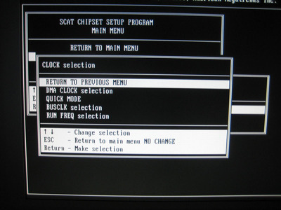
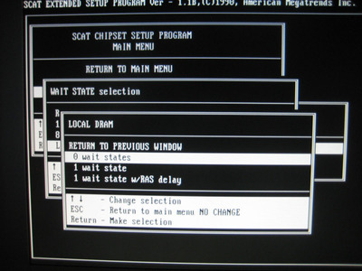
I stupidly overlooked the cmosX section of the BIOS. It's got a bunch of wait state (I/O and RAM) and clock selection options. It was already set to 0 ws for the RAM, though, and I don't think it's quite as fast as some other 12.0 MHz systems at 0WS, but not slow either.

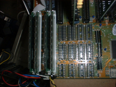
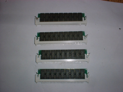
Weird to have a board of this era configure that in the BIOS and not via jumpers, but interesting. I didn't find any RAM size/address space configuration options in that portion of the BIOS and the 384kB relocate doesn't seem to do anything with the DIP RAM. (might only work with SIPPs, even just the 4x 256kB SIMM config)

Landmark 6.0 says it's a 18.5 MHz AT (and drops to 13.87 when I set it to 1 WS) vs my M205 which got 18.41 at 12.5 MHz. (I'm not sure what to think about the D60 chipset now, either it's rather fast at 1WS or slow at 0WS) Though I guess these WS options aren't absolute 0 or 1 WS, but might be +0 or +1 on top of hard-coded chipset waitstates that aren't visible to the user.

Swapping faster oscillators into this 1212C might shed more light on that though.

And yes, I got mine booting DOS 5.0 off the same 170 MB IDE drive I've been playing with for a while (well, it was a matched pair, but its twin seems to have died or gotten even flakier ... no click of death and the bearing/motor whine isn't any worse than it was, but just gives disk failure errors now).

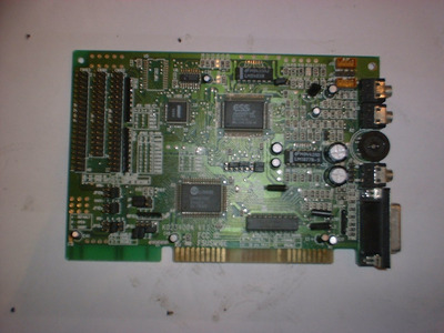
It ran wolfenstein 3D fine with sound blaster sound and all. (actually playable at the default screen size, though I swear Wolf3D runs fast+choppy and twitchy on the 286, and feels too-fast and choppy/twitchy at 20 or 25 MHz, like it uses different code than when on a 386 or higher ... maybe it's keyboard polling, but is fairly normal feeling at 12 MHz here ... though might be painful to play at higher difficulty settings)

X-Wing works, but only with no sound since I couldn't get XMS or EMS detected, DOS loaded low, 580 kB available. (no UMA detected either, I think, though DOS 5 doesn't have as complete a mem table as 6.2) It's slow of course, but does run, 3D renderer/sim engine included. (Wing Commander would be better suited ... or Lucasfilm's Secret Weapons of the LW trilogy)
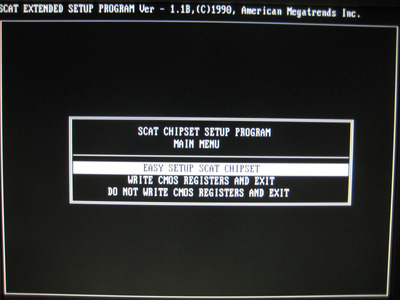
I want to say AMI BIOSs are less trouble, and it seemed the case when I swapped one into my ACT based EAT-12 board (instead of the Quadtel one) but that was a very limited sample size there and I can't even re-try it now as that board has stopped posting. (I may have just worn out the already oxidized RAM sockets swapping chips too many times, but it might be something else ... that hard drive died at the same time, so it's even more confusing)

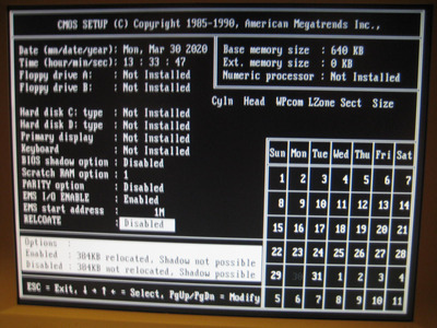
If nothing else, the AMI BIOS has a more familiar interface and layout if you're used to AMI and Award (and maybe some vintages of Phoenix), though it's just hitting escape and y/n to save rather than F10, but still normal page up/down for select and such. (the Quadtel one was weird/annoying using function keys for variable select) Albeit, like some other late 80s or 1990 vintage AMI bioses (or all 286 ones?) numlock is only partially recognized, so you can start typing in digits and accidentally hit the up or down arrow. (I keep forgetting that and get through the 1011 cylinders, 15 heads, 1010 Landing zone, 1 precomp, and then arrow-down when I got to type 22 sectors 🤣 )

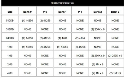
And I haven't tried SIPPs yet successfully, but my board won't post with both types installed (or even 1 SIPP installed), and it definitely seems stuck at seeing only 640kB of the 1MB DIP chips installed. Maybe they cheaped out and simply supported 640kB addressing there, but allowed either 8x 1Mbit chips or 4x 1M + 4x 256kbit ones to be used for the same purpose. (useful when the 1Mbit 256kx4 are more available, but also kind of lazy)

The D60 (and I think HT12) boards with DIP + SIPP/SIMM sockets don't tend to do that, so hopefully nothing's wrong with my board. (it SHOULD do 4MB fine and probably allows EMS + XMS together, so would be in that class of 386-competitive 286 boards, short of actual 32-bit protected mode software, of course)

Anyway, I'll post a BIOS image when I can. There must be programs capable of backing up the BIOS. I mean, the address space is readable to the OS, so there's no reasons such utilities shouldn't exist. (I just haven't used them before) Some later BIOSes (especially board-flashable ones) have built-in utilities for dumping/backing up, but that's not relevant here.

A quick google search a few days ago pointed to some similar discussions and links to utilities, but the links I found were outdated and dead. (but I didn't do that exhaustive a search, and none of those discussions were on vogons, one was on the vintage computer federation forum)

Judging by the indent under the sticker, my board also uses a windowed EPROM, not a cheaper PROM or an EEPROM, so I should be at least a little careful of light exposure, though the metallic gold colored sticker seems intact (in spite of some razor slashing for those dumb warranty stickers) but I won't tempt fate there either. (admittedly, my only dead BIOS is on an Acer turbo XT board with partially peeled off plain white paper sticker, but still)

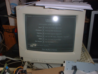
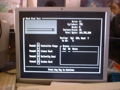
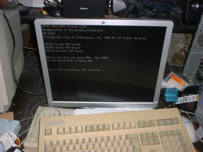
I've got screenshots already, too, but I'll have to upload those later. (camera pics of monitor, not nicer frame captures, but still they're all legible and no CRT scan artifacts ... I guess that's one advantage of using an old GEM LCD monitor, too, on top of the portability ... though the built-in speakers are also convenient)

Reply 59 of 176, by kool kitty89

User metadata
Rank Member
Rank
Member

Here's some BIOS setup pics.

I tried the SIPP sockets and with 4x 256kB modules it detected the same 640kB as the DIPS. With 2 1MB ones it gave me 512kB, then all 4 1MB 70 ns SIPPs I have did 512kB as well. And trying the 256k SIPPs again also gave 512kB (doesn't seem to detect bank 1, but does require bank 0 installed to show 512kB). Same behavior when trying the original DIP chips.

I'm not sure what I could've done or why the 1MB SIPPs would make it freak out. The auto-detect for RAM on these boards seems to be grounding related (checks which sockets have ground pins engaged) and my D60 boards will see even dead DRAM chips as installed and fail them on memory test independently (though only the lower 1MB and XMS RAM get tested, additional EMS will not show POST errors or show up in the ram test, I discovered). So maybe there's a grounding problem somewhere on the board that was making it forced into 640kB mode (512kB bank 0 + 4x 64kx4-bit DRAMs in bank 1) or something like that. That or some non-user-visible CMOS ram/register parameters got set erroneously and are stuck like that. (I don't see a CMOS clear jumper and shorting the battery contacts didn't do the trick, so I'm not sure what to do ... maybe try desoldering the battery and shorting them again)

I suppose some of the minor scratches on the pcb might be doing some weird things to some of the data or address lines. Nothing looks like a cut trace, but I suppose a scrached trace might have some weird stray capcitance or something going on if the scratch just got through the insulating layer. (I haven't mapped out the traces with scratches on them)

I suppose it could be a problem with one of the ceramic, film, or tantalum caps (don't see any electrolytic) or a bad resistor or maybe TTL chip or transistor or something weird like that. But I'm not sure what installing the 1MB SIMMS would have to do with it. (maybe if there's a ttl chip that has something do do with address decoding it could've screwed up the auto-detect in the chipset+BIOS and got it stuck that way)

Swapping the original NMOS Siemens CPU back in didn't change anything, and while possible, I don't think it's dirty or bent contacts on the socket causing this. (I've heard CMOS and some TTL chips don't always play nice together in circuits only tested/intended for NMOS logic, but that doesn't seem to be the problem here, and besides it came with CMOS DRAM installed)

I think I'll just leave this board alone until I can backup the BIOS as it seems to work well enough as-is for that. (though with 512kB I can no longer play around with Wolf3D or X-Wing, but I doubt a real-mode BIOS dumping utility would require more RAM than the ~450 there is now with DOS loaded)

Additionally, JP8 next to the keyboard socket is just there to supply the 5V line to the keyboard. On my board there's also 2 pin sockets with 'FUSE' printed next to them that follow the same traces as that jumper. So I assume that jumper is used to bypass the fuse circuit there. (mine came with no fuse, though it's neat to see a socket for a pico fuse rather than just solder pads)

Attachments