VOGONS


First post, by tammis

User metadata
Rank Newbie
Rank
Newbie

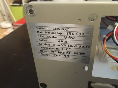
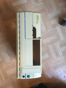
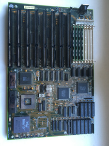
A couple of weeks ago, I got this PC from my uncle, as he didn't need it anymore. First order of business for me was to open it up and see what exactly it was I was dealing with. The motherboard had a Varta battery that had leaked all over the place. I took it off, and despite the corrosion looking really bad, all the traces were intact. Next, I took the hard drive out and connected it to a modern machine. To my delight, the drive was functional, so I imaged it.

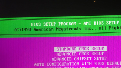
Following that, I tried to boot the machine. It didn't POST, but the PSU seemed to be good. I found a shorted capacitor on the −12 V rail. After replacing that, the machine POSTed just fine, and after setting the correct HDD settings in the BIOS, it booted into DOS 6.22 / Windows 3.11.

So far so good. I wanted to get the computer to retain settings when disconnected from mains (even though there are no RIFA caps in the PSU, I don't feel comfortable leaving it connected when I'm not using it). So, I ordered this drop in replacement 3.6 V NIMH barrel battery and soldered it in. However, the machine still wouldn't retain any settings, and, on top of that, some power cycles later, the keyboard suddenly cut out completely when I was in the BIOS settings.

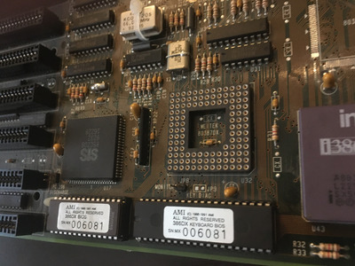
Now, the BIOS gives a Keyboard error almost every time on power up (in addition to the CMOS errors). Sometimes, however, I get a KB/Interface error instead. I have verified that there is continuity from each pin of the female DIN connector to the board, so the connector should be fine. There is also continuity between the data and clock pins of the connector and the corresponding pins of the keyboard controller chip. I have no means of checking whether the keyboard itself works or not (actually, I cannot even manage to open it up, it having no screws). The keyboard is a crappy Keytronic rubber dome one.

I have since removed the new battery, but the keyboard problem remains.

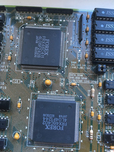
I don't really know that much about computers, but I'd like to get this one up and running again. So, I would appreciate any pointers about how to proceed. Also, Google doesn't seem to know anything about this manufacturer (Pilot Computer), and I cannot locate any identifications on the motherboard silk screen, either. So, if anyone recognizes the model, that info would also be appreciated.

Attachments

  • IMG_4586.JPG
    Filename
    IMG_4586.JPG
    File size
    1.38 MiB
    Views
    624 views
    File comment
    back panel badge (in Finnish)
    File license
    Public domain
  • IMG_4585.JPG
    Filename
    IMG_4585.JPG
    File size
    1.31 MiB
    Views
    624 views
    File comment
    case
    File license
    Public domain
  • IMG_4584.JPG
    Filename
    IMG_4584.JPG
    File size
    1.77 MiB
    Views
    624 views
    File comment
    BIOS
    File license
    Public domain
  • IMG_4583.JPG
    Filename
    IMG_4583.JPG
    File size
    1.68 MiB
    Views
    624 views
    File comment
    chipset
    File license
    Public domain
  • IMG_4582.JPG
    Filename
    IMG_4582.JPG
    File size
    1.87 MiB
    Views
    624 views
    File comment
    motherboard
    File license
    Public domain

Reply 1 of 9, by Horun

User metadata
Rank l33t++
Rank
l33t++

To me it looks almost identical to MICRO EXPRESS, INC. 80386-33/40 = MicroHouse #MH1086: http://www.uncreativelabs.de/th99/m/M-O/31086.htm
The the board description, layout and jumper locations seem exact, the front panel header seems exact. The cache jumpers in TH99 say: JP6, JP61, JP62 but on your board are labeled 6A, 6B, 6C but appear to be same settings.

Hate posting a reply and then have to edit it because it made no sense 😁 First computer was an IBM 3270 workstation with CGA monitor. Stuff: https://archive.org/details/@horun

Reply 2 of 9, by tammis

User metadata
Rank Newbie
Rank
Newbie

Thanks for the identification! It does indeed look very similar.

I managed to get the keyboard working again. It was a novice mistake, the DIN plug just wasn't "all the way there" in the connection. 🤣

Now that I have the jumper schematics, I'm going to try my luck with the external battery header and 4 AA batteries (going to remove the JP3). I'm waiting for parts.

Reply 3 of 9, by tammis

User metadata
Rank Newbie
Rank
Newbie

I assembled an external battery with a 4x AA (in series) battery holder and a 4-pin 2,54 mm connector. I don't have any crimping tools, so the process was quite hard, but I managed to get a stable connection between the battery holder wires and the two outmost pins of the connector.

I removed the Jp3 jumper and connected the connector to the external battery header so that the minus pin of the connector is connected to the ground-connected pin on the header and the plus pin to the other side. I have verified around 6 V of DC voltage between the pins. However, the CMOS settings still refuse to stay when disconnected from mains, and the BIOS still gives a CMOS battery state low error. My guess is that the connection between the connector and the mobo header is not constant (the connector feels a bit loose when connected), but is there some other (maybe obvious) things I am overlooking?

The PC doesn't have a sound card, so I am contemplating building a connection between the PC speaker header and my OSSC with these instructions (using the 3,5 mm plug option at the OSSC's end): http://deinmeister.de/e_sbpcqlnk.htm Let's see how that goes...

Reply 5 of 9, by tammis

User metadata
Rank Newbie
Rank
Newbie

I managed to source a Sound Blaster AWE 32 PnP (CT3670), which I have now successfully installed into the machine. I also wired the PC Speaker sounds from the PC Speaker header on the mobo to the PC Speaker input header on the sound card. All of this is working surprisingly well.

The battery issue is kind of intermittent. I soldered the connectors to the external battery header pins and am measuring solid 6.3 V across the pins. On cold boots after being disconnected from mains, the computer sometimes retains the settings and sometimes not, giving a CMOS battery state low error. Given that there isn't that much to dial in, I'll let it be for now.

I am now running the audio and video from the computer like so: 386 pc -> OSSC -> capture card on a modern machine -> modern OLED display.
The audio is working perfectly. The video has crazy vertical artefacting going on (both on display and when monitoring the capture signal in OBS), but tbh, I was surprised that the display even accepted the weird 70 Hz HDMI signal.
The OSSC is running bone stock settings, so I would appreciate any pointers on how to dial in some settings that would alleviate the artefacting, in the case that it is due the upscaling and not the VGA card itself.

Reply 6 of 9, by darry

User metadata
Rank l33t++
Rank
l33t++
tammis wrote on 2020-08-02, 17:32:
I managed to source a Sound Blaster AWE 32 PnP (CT3670), which I have now successfully installed into the machine. I also wired […]
Show full quote

I managed to source a Sound Blaster AWE 32 PnP (CT3670), which I have now successfully installed into the machine. I also wired the PC Speaker sounds from the PC Speaker header on the mobo to the PC Speaker input header on the sound card. All of this is working surprisingly well.

The battery issue is kind of intermittent. I soldered the connectors to the external battery header pins and am measuring solid 6.3 V across the pins. On cold boots after being disconnected from mains, the computer sometimes retains the settings and sometimes not, giving a CMOS battery state low error. Given that there isn't that much to dial in, I'll let it be for now.

I am now running the audio and video from the computer like so: 386 pc -> OSSC -> capture card on a modern machine -> modern OLED display.
The audio is working perfectly. The video has crazy vertical artefacting going on (both on display and when monitoring the capture signal in OBS), but tbh, I was surprised that the display even accepted the weird 70 Hz HDMI signal.
The OSSC is running bone stock settings, so I would appreciate any pointers on how to dial in some settings that would alleviate the artefacting, in the case that it is due the upscaling and not the VGA card itself.

AFAIK, most HDMI capture cards can't handle 70Hz input, so you would probably want to use something (another scaler) to convert to 60Hz before feeding the capture card . OSSC cannot convert refresh rates .

Have you tried the OSSC directly connected to the monitor ?

What setting are you using for output on OSSC for 400 line mode (can't remember what default is) ?

What model capture card and monitor are you using ?

Reply 7 of 9, by tammis

User metadata
Rank Newbie
Rank
Newbie
darry wrote on 2020-08-02, 18:50:
AFAIK, most HDMI capture cards can't handle 70Hz input, so you would probably want to use something (another scaler) to convert […]
Show full quote

AFAIK, most HDMI capture cards can't handle 70Hz input, so you would probably want to use something (another scaler) to convert to 60Hz before feeding the capture card . OSSC cannot convert refresh rates .

Have you tried the OSSC directly connected to the monitor ?

What setting are you using for output on OSSC for 400 line mode (can't remember what default is) ?

What model capture card and monitor are you using ?

The capture card is an Elgato HD60 Pro (PCIe). The default for 400p is line-doubling, so the output is (if I understand correctly) 1280x800 @ 70 Hz. The reading on the OSSC:s own display is "AV3: RGBHV 449p 31.46kHZ 70.08Hz".

The monitor is a Philips BDM3270QP2 32". Bypassing the capture card makes no difference – in fact, the artefacting is present even when the computer is connected to a generic early-2000s 4:3 LCD display (HP L1950g) directly via VGA.

Here's a closeup picture of the BIOS when displaying on the Philips with a 1:1 aspect ratio setting:

Attachments

  • IMG_4690_cropped.jpg
    Filename
    IMG_4690_cropped.jpg
    File size
    318.26 KiB
    Views
    459 views
    File comment
    artefacting
    File license
    Public domain

Reply 8 of 9, by maxtherabbit

User metadata
Rank l33t
Rank
l33t

your issue is the sample rate - on the OSSC change "400p in sampler" to VGA 720x400@70 if you want the text mode to look correct

unfortunately this makes 320x200 VGA games look terrible, so you have to put the setting back to the default VGA 640x400@70 when changing from DOS/BIOS text to a game

Reply 9 of 9, by tammis

User metadata
Rank Newbie
Rank
Newbie
maxtherabbit wrote on 2020-08-02, 20:27:

your issue is the sample rate - on the OSSC change "400p in sampler" to VGA 720x400@70 if you want the text mode to look correct

unfortunately this makes 320x200 VGA games look terrible, so you have to put the setting back to the default VGA 640x400@70 when changing from DOS/BIOS text to a game

Thanks! This is indeed the case. With the default settings, text-based graphics have the artefacting and the graphical applications don't. If I switch to 720x400, the text-based graphics look sharp but the graphical applications get the artefacting. Good to know. I noticed that the capture card doesn't accept the text mode signal but the Philips display does.