VOGONS


Reply 20 of 31, by fool

User metadata
Rank Member
Rank
Member

According to datasheet, cacheable RAM with 512kB L2 is full 128MB, if tag SRAM is 32Kx9 (and they should be).
With 256kB L2 cacheable area is 64MB using same tag chips.

cacheable.JPG
Filename
cacheable.JPG
File size
120.18 KiB
Views
650 views
File license
Public domain

Toshiba T8500 desktop
SAM/CS9233 Wavetable Synthesizer daughterboard
Coming: 40-pin 8MB SIMM kit, CS4232 ISA wavetable sound card

Reply 21 of 31, by Horun

User metadata
Rank l33t++
Rank
l33t++
AvalonH wrote on 2020-10-16, 22:04:

Finished scanning the manual, took awhile, 94 pages!! lot of excercise running up and down stairs to the scanner and trying not to damage the manual.
I have attached it to this post, front inside page of manual states it is manual revision 1.2, dated August 1994, and for mainboard Rev 1.6 and up.

One thing, do you guys know how much memory this board (Aries chipset) can cache. Can't find any info on this in the forum or google. I only have 32MB but the board supports up to 128MB. Can it cache the full 128MB??

Thanks ! Added it to Vogons Driver Library: http://www.vogonsdrivers.com/getfile.php?file … 8&menustate=0,0

Hate posting a reply and then have to edit it because it made no sense 😁 First computer was an IBM 3270 workstation with CGA monitor. Stuff: https://archive.org/details/@horun

Reply 22 of 31, by cyclone3d

User metadata
Rank l33t++
Rank
l33t++

Ok, I have the Glitchworks DS12887 replacement installed and getting ready to mod how the clockgen is set up.

That should give me the full regular fsb range.

Noticed in another thread about a board with the same clockgen and saw that if PIN 6 is asserted low, it will lower the CK output to 8Mhz, which the chipset will halve to 4Mhz. So maybe I will have some fun with a 4Mhz fsb IF it works.

Once I get the mods done, I will probably end up making a clock doubler like the one I linked previously so maybe I can get a 50Mhz and maybe a 60Mhz fsb, but I kinda doubt that will work.

Edit:
Just noticed that this board has build in support for using the same type of Dallas chip that Glitchworks uses. There is a location for a battery and extra clock crystal mounted directly on the board. I verified this by confiming that the leads have continuity with the pins that the Glitchworks replacement uses.

Yamaha modified setupds and drivers
Yamaha XG repository
YMF7x4 Guide
Aopen AW744L II SB-LINK

Reply 23 of 31, by cyclone3d

User metadata
Rank l33t++
Rank
l33t++

So here are some pics of the mods:
MX-8315PC clockgen removed.

MX-8315_removed.jpg
Filename
MX-8315_removed.jpg
File size
429.73 KiB
Views
610 views
File license
Fair use/fair dealing exception

Socket installed - I cut down a 20-pin socket I pulled out of a dead ISA I/O card.

socket_installed.jpg
Filename
socket_installed.jpg
File size
620.28 KiB
Views
614 views
File license
Fair use/fair dealing exception

Pull down jumper for 8 Mhz clock. This is supposed to gradually reduce the CK clock to 8Mhz (fsb clock being fed into the chipset). This ended up being super easy because all I had to do was install a jumper to
short across the capacitor that was already there. Took two pins I pulled from a dead motherboard, bent the one end at a 90 degree angle and soldered them on.
Spacing was also perfect as-is.

Pull_down_jumper_for_8Mhz_CK_installed.jpg
Filename
Pull_down_jumper_for_8Mhz_CK_installed.jpg
File size
102.83 KiB
Views
614 views
File license
Fair use/fair dealing exception

MX-8315PC clockgen socketed with the S2 leg bent out.

MX-8315_socket_and_S2_leg_bent_out.jpg
Filename
MX-8315_socket_and_S2_leg_bent_out.jpg
File size
339.43 KiB
Views
610 views
File license
Fair use/fair dealing exception

S2 jumper installed.
I used the one leg of the D-bracket that holds down the 14Mhz crystal for mounting the ground leg of the jumper.
Then I used one of the left over legs from the socket I cut down, soldered it to one end up a wire, then heat-shrinked it. I didn't want to solder directly to the clockgen and this worked like a charm.
Ran the wire over next to the ground leg so I could cut it to size. Soldered another pin to the other end of the wire, heat-shrinked it, bent it 90 degrees and then used a 2-pin jumper guide and super glued both legs to it so it would stay in place.

S2_jkumper_installed.jpg
Filename
S2_jkumper_installed.jpg
File size
380.06 KiB
Views
614 views
File license
Fair use/fair dealing exception

Yamaha modified setupds and drivers
Yamaha XG repository
YMF7x4 Guide
Aopen AW744L II SB-LINK

Reply 24 of 31, by cyclone3d

User metadata
Rank l33t++
Rank
l33t++

Now that I did some testing, I think for some reason the board is stuck at 8Mhz FSB. Maybe I fried the capacitor when soldering the jumper leads onto it though, according to the data sheet, that shouldn't have anything to do with it since it is pulled high internally. From what I could find, jumpering it to ground should pull it low to bring it down to 8Mhz FSB. There is NOT a short across the capacitor.

Could have also fried the clockgen when I desoldered it I guess. I can order some more but the way it is behaving makes no sense. Maybe I just need to remove the clockgen and reseat it.

Going to take the board out again and double check all the connections to make sure I didn't miss something.

Yamaha modified setupds and drivers
Yamaha XG repository
YMF7x4 Guide
Aopen AW744L II SB-LINK

Reply 25 of 31, by fool

User metadata
Rank Member
Rank
Member

board is stuck at 8Mhz FSB

How about the jumper on turbo switch? Maybe it pulls down the same pin6 ?

Toshiba T8500 desktop
SAM/CS9233 Wavetable Synthesizer daughterboard
Coming: 40-pin 8MB SIMM kit, CS4232 ISA wavetable sound card

Reply 26 of 31, by cyclone3d

User metadata
Rank l33t++
Rank
l33t++
fool wrote on 2020-11-27, 16:09:

board is s

tuck at 8Mhz FSB

How about the jumper on turbo switch? Maybe it pulls down the same pin6 ?

It doesn't. Already tested that.

Basically, no FSB jumpers make any difference now. Turbo switch/jumper being on or off doesn't make a difference either.

Yamaha modified setupds and drivers
Yamaha XG repository
YMF7x4 Guide
Aopen AW744L II SB-LINK

Reply 27 of 31, by cyclone3d

User metadata
Rank l33t++
Rank
l33t++

Well, I took the motherboard out of the case and tested all the connections. Nothing is shorted and everything has continuity that should.

Everything seems to be good so my guess is that I most likely killed the clockgen when I removed it.

Just ordered 10 of them and still had to pay more for shipping than for the chips themselves.

I'll update when the new chips come in.

If that doesn't fix it, then I will try to replace the one surface mount capacitor that I mounted the jumper to.

Yamaha modified setupds and drivers
Yamaha XG repository
YMF7x4 Guide
Aopen AW744L II SB-LINK

Reply 28 of 31, by cyclone3d

User metadata
Rank l33t++
Rank
l33t++

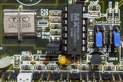
Another update. Got the new clockgen chips in and as luck would have it, that wasn't the problem. Was looking around and decided to check the resistance of the capacitor that I had hooked the jumper pins to. It was somewhere around 20k ohms
which could have also been reading something elsewhere in the circuit.

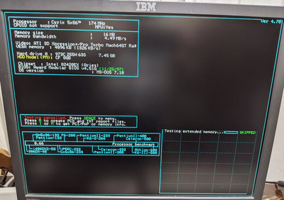
Decided to power it up right after taking the reading and the clock speed wasn't stuck at a reported 16Mhz... hmmm. Tried a few more times and it dropped back to a reported 16Mhz.. hmmmm.

Did the multimeter reading again and then powered on again and it wasn't at 16Mhz again.

So I think I must have damaged the capacitor when soldering the jumper pins on in a way that the capacitor was acting like a low resistance resistor or a dead short after charging.

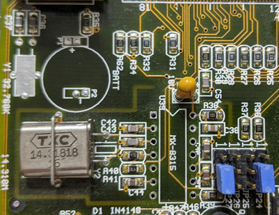
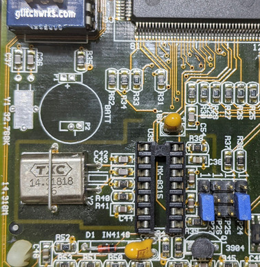
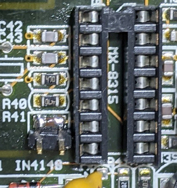
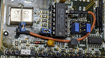
I desoldered the jumper pins and the capacitor and it is not stuck at 16Mhz anymore.

Looked at the datasheet for the clockgen again and there is no mention of there needing to be anything between pin 6 and ground unless you want to pull it low to drop the clockgen frequency to 8Mhz.

I'm not going to put a capacitor back in the circuit and if I run into a problem, I'll make a jumper with a capacitor attached and will swap back and forth when I change speeds... at least for the time being.

Edit:
It is still acting up... grrrr.

Edir 2: Think I got it. Ran my meter probe around where I had soldered (with it powered off... duh!) There must have been a little bit of something shorting something together because now after multiple power cycles and different CPUs, it is working as expected. YAY!

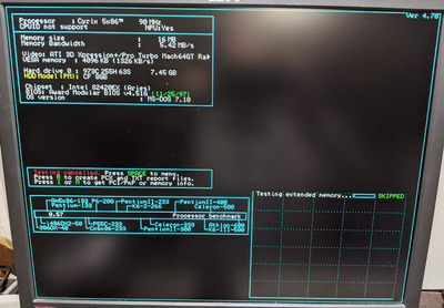
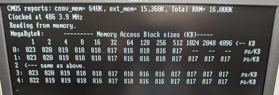
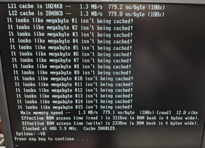
Now I can get it going and run some more tests.

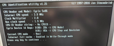
Removing and adding the jumper that brings it down to 8Mhz clock output works just fine. This means I should be running a 4Mhz FSB... and with a 1x multiplier CPU or a POD CPU with the fan removed I should be able to get down to 4Mhz CPU speed.

For now I am going to bed... I'll mess with it tomorrow if I have the chance.

Yamaha modified setupds and drivers
Yamaha XG repository
YMF7x4 Guide
Aopen AW744L II SB-LINK

Reply 29 of 31, by cyclone3d

User metadata
Rank l33t++
Rank
l33t++

Here is the Cyrix 5x86 120 with 2x multiplier at 4Mhz fsb with caches disabled

Check out the CPU score of only 0.66

Cyrix_5x86_8Mhz_No_cache.jpg
Filename
Cyrix_5x86_8Mhz_No_cache.jpg
File size
400.78 KiB
Views
535 views
File license
Fair use/fair dealing exception

It broke the CPU Mhz detection... hehe.

Edit: This is with the CPU type selection set to:
SL Enhanced
486DX & ODP
DX2 & ODP
486DX4
(JP18 & JP19 2-3, 3-4)

The pull of the multiplier jumper while running doesn't work with it set to this.

When CPU type is set for Pentium Overdrive it does work. Running benches at a reported ~2Mhz FSB and 4Mhz CPU.

On a side note, the BIOS always detects the Cyrix 5x86 as an 80487SX no matter the jumper settings.

After these tests, I'll stick in a POD, gimp it to 1x and then run benches.

Yamaha modified setupds and drivers
Yamaha XG repository
YMF7x4 Guide
Aopen AW744L II SB-LINK

Reply 30 of 31, by cyclone3d

User metadata
Rank l33t++
Rank
l33t++

Here are some benches at a reported 1.9Mhz FSB. Now cachechk is broken and thinks there are 12x cache levels.

L1/L2 on/off don't matter at this speed anymore.. at least in Speedsys as the CPU bench stays the same.

This is great. I'll try to bench with a POD and a 1x multiplier 486 tomorrow.

Cyrix_5x86_4Mhz-1.jpg
Filename
Cyrix_5x86_4Mhz-1.jpg
File size
297.59 KiB
Views
532 views
File license
Fair use/fair dealing exception
Cyrix_5x86_4Mhz-2.jpg
Filename
Cyrix_5x86_4Mhz-2.jpg
File size
411.36 KiB
Views
532 views
File license
Fair use/fair dealing exception
Cyrix_5x86_4Mhz-4.jpg
Filename
Cyrix_5x86_4Mhz-4.jpg
File size
334.34 KiB
Views
532 views
File license
Fair use/fair dealing exception
Cyrix_5x86_4Mhz-3.jpg
Filename
Cyrix_5x86_4Mhz-3.jpg
File size
417.5 KiB
Views
532 views
File license
Fair use/fair dealing exception

One other thing. This is with Turbo enabled.. not sure what Turbo does right now, but with the Cyrix 5x86 it acts like a halt when I disable it. Either that or it is going so slow that I need to leave it for a very long time to see it do anything.

Yamaha modified setupds and drivers
Yamaha XG repository
YMF7x4 Guide
Aopen AW744L II SB-LINK

Reply 31 of 31, by cyclone3d

User metadata
Rank l33t++
Rank
l33t++

So I tried setting the multiplier on the Cyrix 5x86 to 1x and I get the same exact benchmark result in speedsys as when I set it to 2x and then remove the jumper after booting.

However, some other benchmarks show a lower speed with the jumper trick than with Setmul.

I also tried an Intel 486DX-50 and it was faster at 4Mhz than the Cyrix was.

Also tried a POD83 at 4Mhz and it was even faster than the 486DX-50 was at 4Mhz.

Going to see if I can lower the Cyrix performance anymore by messing with the registers though I am pretty certain that none of them are enabled by default on this board.

I was really hoping to get below the 6-in-1 Turbo-switched Socket 7 system which came in with a low score of 0.45 compared to my 0.57.
WIP 2: The 6-in-1 Turbo-switched Socket 7 - from XT to 500MHz; dual Tseng powered...

Yamaha modified setupds and drivers
Yamaha XG repository
YMF7x4 Guide
Aopen AW744L II SB-LINK