First post, by jdgabard
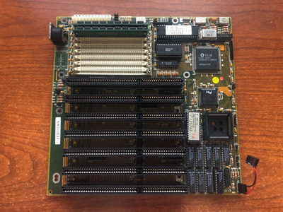
So I'm attempting to repair a 386sx MB that I received a little while back. The board is identical to this board on Stason.org, although without markings it's hard to say for sure: https://stason.org/TULARC/pc/motherboards/M/M … 386-A-B307.html
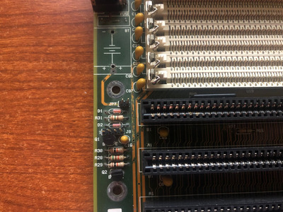
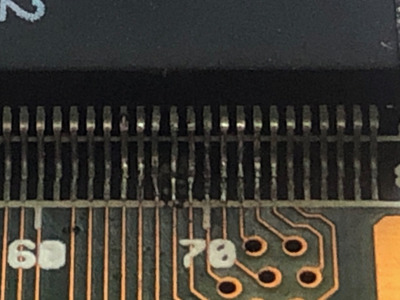
This board came with a Varta battery installed, and there was a decent amount of corrosion around the keyboard connector. I cleaned and neutralized it, and then looked for damage. While there was some corrosion, no traces were broken, at least as far as I can see... The only other damage I could see around the board was a small amount of corrosion around the VL82C311 IC (far opposite side of the board strange enough). Several of the IC legs had come unsoldered, and I repaired these and tested for connectivity to the nearby vias. The repair appears to have been successful.
The motherboard is not completely dead. Upon boot I get 10 short beeps, AMI beep code: CMOS shutdown register read/write error.
But I'm not entirely sure what this beep code is referring to. Now, knowing quite a bit about early computer design, I am making an assumption that this is either a hardware register within the 82C311, or they're using one of the 74LS373 octal latches as a register and one or the other is not functioning properly. But before I decided to start desoldering ICs, I wanted to get some input from others.
Anyone got any suggestions?