VOGONS


First post, by Aui

User metadata
Rank Member
Rank
Member

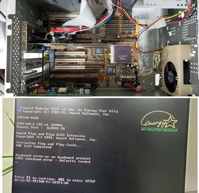
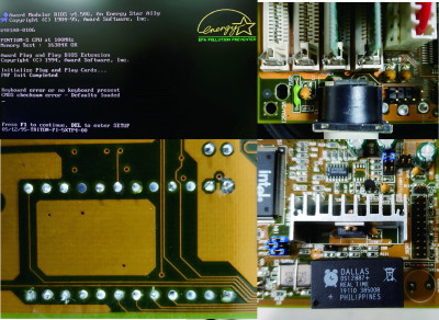
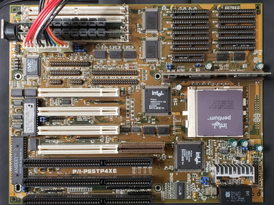
Hi everyone - my first post. Thanks for the great support. I have reached a dead end, trying to restore an old PC I found on a dump. The Computer has a P1 100 Mhz and sits on an Asus P/1-P55TP4XE. The Dallas RTC was flat (causing all sorts of errors), but I could still boot up into Dos and everything was more or less working. So I decided to replace the battery, desoldered it and soldered in a new Dip socket attached a coin cell to the Dallas RTC (and bought a second new one) and put everything back together. And now, the PC is no longer booting correctly. The key issue is the Keyboard (old 5 pin AT conector) which is not working. I have no other old PC to test the keyboard nor do I have another old AT style keyboard to test if that would work. Generally, I doubt that the keyboard should have gone bad - just the moment I replaced the RTC. Replacing the RTC has also not soved the CMOS checksum error. Any ideas what could have gone wrong. Also any ideas how I could get another keyboard working on this board would be much appreciated. Processor, Ram and PNP cards are still correctly initialized (see attached screenshot). What are my options. I have put in so much time into this thing, I cant yet convince myself to get a new board. Thanks for any suggestions already in advance.

Attachments

  • Asus_MB.jpg
    Filename
    Asus_MB.jpg
    File size
    43.42 KiB
    Views
    1046 views
    File license
    Public domain

Reply 1 of 10, by sf78

User metadata
Rank Oldbie
Rank
Oldbie

And you're 100% sure that you scraped out the correct solder spots for the battery wires and the connection is solid? Did you measure the voltage from the solder spots to make sure it's OK? The error might disappear once you get to BIOS to change and save current settings.

Reply 2 of 10, by Benedikt

User metadata
Rank Oldbie
Rank
Oldbie

I guess it's time to go through the checklist:

  • Did you work in an ESD-safe environment while handling the motherboard?
  • How smoothly did the desoldering go? Could you have pulled out a VIA?
  • Is the new RTC chip compatible and inserted the right way around?
  • Does the keyboard work on a PS/2 port with an adapter? (You could improvise one. It's just a different plug.)
  • Does a PS/2 keyboard work with this machine with an adapter?

Reply 3 of 10, by Aui

User metadata
Rank Member
Rank
Member

Thanks for the quick response.
Regarding the RTC, I think I connected the coincell correctly. If I remove it I get an additional error message (something like CMOS battery flat). I also have an additional "new" Dallas battery (probably some remake). I dont like to use it, because the pins are much thinner and it does not firmly sits in the dipsocket, but when it connects I get the same error message. I also jumpered the board to clear the CMOS, no effect.
Regarding the soldering: it went reasonable well. I checked the new solderjoints of the replaced dipsocket under a microscope, and the connections I can see look good and seem to connect to the respective circuits on the board (only half of them are on the lower side of the board and visible).
I can not completely rule out, that something was broken during soldering, however, If I had broken something seriously, I would not expect the board to boot up so far.
regarding the Adapter: Yes, probably the logical next step. Maybe it really is the Keyboard. Thanks for the help.

Reply 4 of 10, by mkarcher

User metadata
Rank l33t
Rank
l33t

The two failing devices (Keyboard, RTC) are connected on the "X-Bus". That's an 8-bit data bus interconnected to the ISA bus via a buffer chip, usually a 74F245, as this is the chip type recommended by Intel. An interesting test might be booting with an ISA graphics card to check whether the ISA bus already behaves strangely (garbled screen or beeps), or the problem seems limited to the X-Bus.

As I suppose you only soldered near the RTC, it's unlikely that you damaged the KBCS# trace thats selecting the keyboard controller, but some signal that connects to both the KBC and the RTC, and this is the 8 data lines. So, the first thing I would check if KBC and RTC start failing at the same time is accidental shorts between the data pins D0-D7 on the X-Bus. There is a catch with the theory that shorted data lines on the X-Bus are causing the problem: The BIOS chip usually is also connected to the X-Bus data lines, but the BIOS chip obviously works fine. The board layout makes it unlikely that data lines at the KBC are working, but are non-functional at the BIOS chip.

Reply 6 of 10, by jmarsh

User metadata
Rank Oldbie
Rank
Oldbie

Check if the LEDs on the keyboard do anything at all when powering up the system, also check if the fuse next to the keyboard port has continuity (should have very low resistance, sometimes when they fail they still conduct at a few hundred ohms).

Reply 7 of 10, by Aui

User metadata
Rank Member
Rank
Member

Thanks everyone for the good suggestions. The keyboard is not quick-lighting up when powering on. My next step will be an 5pin - Ps2 adapter. If that is not working I will check the other suggestions and post an image of the solder connections. May take a few days. I already have a "new" Dallas chip. But is has very thin legs, so it barely connects to the socket. I need to wiggle it 20 times before getting a single boot up (as described above) The old one, despite the desoldering sits much better. It always boots up to "No Keybord..., CMOS Error..."(see screenshot)
If I remove the coincell it gives an additional error message (saying CMOS battery failure). One thing that strikes me is why I still get the CMOS checksum error? If the keybard is really bad, then thats that. But this CMOS error still suggests, that something is not right somewhere between the RTC and the Bios chip.

Reply 8 of 10, by Aui

User metadata
Rank Member
Rank
Member

Hi again, I made a little progress, but no success. I was able to find a Keyboard adapter as well as an old 5-pin AT Keyboard. In both cases the error message remained unchanged. I was not able to get an ISA graphic card yet, have to wait for one with a reasonable price/shipping. As requested, I attach another few images including the Keyboard connector and the underside of the Socket I have soldered in. The image is probably barely good enough to really see much. Well - this board looks like new and yet, it seems I finished it. 🙁
Is there any way to circumvent that 5pin adapter (e.g. a PCI card with a Keyboard connector - and would the BIOS accept such an "early Keyboard" perhaps already found during PCI init. (which seems to work fine (see attached image) ?
Any suggestions would be much appreciated.

Attachments

  • MB-2.jpg
    Filename
    MB-2.jpg
    File size
    1.82 MiB
    Views
    784 views
    File license
    Public domain
  • 20210115_174027.jpg
    Filename
    20210115_174027.jpg
    File size
    1.46 MiB
    Views
    784 views
    File license
    Public domain

Reply 9 of 10, by treeman

User metadata
Rank Oldbie
Rank
Oldbie

You could test each of the keyboard plug pins with a multimeter to see if there is connectivity to the solder points on the back of the pcb to rule out a faulty plug

Reply 10 of 10, by Aui

User metadata
Rank Member
Rank
Member

Story continues... and now I found the culprit. However, I spotted the problem not before desoldering the dip socket again and resoldering a new one once more.
But then I discovered - it was indeed the Keyboard fuse (as pointed out to me much earlier). However, the fact that the fuse is faulty would only show, with the keyboard detached (?). As long as the Keyboard was pluged in, the fuse still showed continuity - obviously there is something here that I dont understand. After bridging the fuse the board boots up without any problems. now I need to find that fuse and replace it. The fact that replacing the socket and the failure of the fuse coincided - caused me quite a headache. The remaining question is - why that fuse blew up. Anyway - thanks again for all the good suggestions!