VOGONS


Reply 160 of 180, by maxtherabbit

User metadata
Rank l33t
Rank
l33t

There is a jumper wire connecting the FPU to the pin 53 trace. My plan is to just cut that and bodge a wire over to pin 47 (system clock) to leave the KBC unaffected.

Reply 161 of 180, by Anonymous Coward

User metadata
Rank l33t
Rank
l33t

So the SCAMP is a fast chipset for a 286, eh?
Supposedly there is a more expensive VLSI TOPCAP chipset for 286 or 386SX as well, but I have never seen a board or system based on it.

"Will the highways on the internets become more few?" -Gee Dubya
V'Ger XT|Upgraded AT|Ultimate 386|Super VL/EISA 486|SMP VL/EISA Pentium

Reply 163 of 180, by pshipkov

User metadata
Rank Oldbie
Rank
Oldbie

So i tried few things with the FPU:
VL82C201:46 (PROC CLK) -> FPU:32 = the original FPU performance the motherboard produces, FPU ticks with the processor frequency
VL82C201:47 (SYS CLK) -> FPU:32 = FPU performance drops slightly compared to the first case
VL82C201:53 (MHZ7) -> FPU:32 = FPU performance drops significantly, looks like FPU internal frequency division is happening because if the higher input frequency.

Still think that frequency multiplier can be a good option to find best configuration.

retro bits and bytes

Reply 164 of 180, by maxtherabbit

User metadata
Rank l33t
Rank
l33t
pshipkov wrote on 2021-03-31, 04:36:
So i tried few things with the FPU: VL82C201:46 (PROC CLK) -> FPU:32 = the original FPU performance the motherboard produces, FP […]
Show full quote

So i tried few things with the FPU:
VL82C201:46 (PROC CLK) -> FPU:32 = the original FPU performance the motherboard produces, FPU ticks with the processor frequency
VL82C201:47 (SYS CLK) -> FPU:32 = FPU performance drops slightly compared to the first case
VL82C201:53 (MHZ7) -> FPU:32 = FPU performance drops significantly, looks like FPU internal frequency division is happening because if the higher input frequency.

Still think that frequency multiplier can be a good option to find best configuration.

What's the logic state of pin 39 on your 287xl? My board holds it high, which gives 1/1 as per the 287xl datasheet. Low is 1/2 of the clock input on pin 32

Reply 166 of 180, by maxtherabbit

User metadata
Rank l33t
Rank
l33t
pshipkov wrote on 2021-04-01, 07:35:

The state of this pin does not make a difference.

That statement directly contradicts the 287XL datasheet from Intel. Unless of course you are using a different FPU?

Last edited by maxtherabbit on 2021-04-01, 23:24. Edited 1 time in total.

Reply 169 of 180, by fixator

User metadata
Rank Newbie
Rank
Newbie
megatron-uk wrote on 2021-01-15, 11:46:
The replacement motherboard arrived today and I have to say that it is in absolutely perfect condition. […]
Show full quote

The replacement motherboard arrived today and I have to say that it is in absolutely perfect condition.

One problem I've got though is that it isn't exactly identical to the Peaktron PA286-SMT. This one is silk-screened as a 'MICRO SYSTEM' MICROCOMPUTER SYSTEMS PA286-SA1 Rev D3A.

At first glance the board is physically identical, but closer inspection shows a few differences to the Peaktron system:

Jumper block SW1 has 9 jumpers on the Peaktron board (1-9), on mine it is 2-9.

The FPU socket has a async/sync jumper on the Peaktron board, there isn't one (or even solder pads for one) on mine.

The Peaktron manual has jumper settings for 512KB - 16MB using combinations of the DIP and SIMM sockets using jumper block SW1 (pins 5, 6, 7, 😎 as well as J7 and J8 elsewhere on the board. I don't have the same number of pins on SW1, and J7, J8 and J9 are labelled in a diferent way and the silkscreen on the board only lists up to 4MB configurations.

I'm a little concerned that the one site I found with reference to PA286-SA1 lists it as performing very fast, but only supporting 4MB (and no mention of 25MHz clock support): https://www.clous.cz/pa286-sa1/

Updated photos to follow.

Can you dump BIOSes from PA286-SMT and PA286-SA1 motherboards?
I have PA 286-16/20/25 & PA 386SX-16/20 combined MB with same chipset and no bios chips 🙁

Reply 171 of 180, by megatron-uk

User metadata
Rank Oldbie
Rank
Oldbie

Coming back to trying to get my Biostar MB1220VE working again whilst waiting for parts on my other boards.

I'm going back through things methodically; firstly checking for the correct clock signals.

ISA B30 (OSC): 14.3MHz clock present

20210423_133918.png
Filename
20210423_133918.png
File size
139.12 KiB
Views
1086 views
File license
CC-BY-4.0

ISA B20 (CLK): 8MHz clock present

20210423_134011.png
Filename
20210423_134011.png
File size
157 KiB
Views
1086 views
File license
CC-BY-4.0

My collection database and technical wiki:
https://www.target-earth.net

Reply 172 of 180, by megatron-uk

User metadata
Rank Oldbie
Rank
Oldbie

On the processor, pin 31 (CLK) is showing a 9.996MHz clock - this is a 20MHz processor running from a 40MHz oscillator.

20210423_135456.png
Filename
20210423_135456.png
File size
148.38 KiB
Views
1082 views
File license
CC-BY-4.0

This ~10MHz input clock to the processor doesn't seem right to me. The CLK pin is defined as being "DIVIDED BY TWO INSIDE THE 80286 TO GENERATE THE PROCESSOR CLOCK" (From the AMD 80286 datasheet).

My collection database and technical wiki:
https://www.target-earth.net

Reply 173 of 180, by Deunan

User metadata
Rank Oldbie
Rank
Oldbie
megatron-uk wrote on 2021-04-23, 13:01:

This ~10MHz input clock to the processor doesn't seem right to me. The CLK pin is defined as being "DIVIDED BY TWO INSIDE THE 80286 TO GENERATE THE PROCESSOR CLOCK" (From the AMD 80286 datasheet).

Frankly I'm not sure how are you figuring the slower clocks are OK with 500ns timebase and pretty obvious signs of aliasing already on the screen. It even says, right at the top, 30MS/s - and then you want to see 40MHz? Which BTW should be close to square wave so your scope amp should be 200MHz or wider BW to even resemble that.

With a decent 20MHz analog scope you could probably go to 5x magnification on 200ns and just barely see that signal, considering it's almost 5Vpp so even at -10dB will still be visible. With only 30Ms/s on a digital scope all you can see is up to 15MHz and only if it's sinusoidal - laws of physics and math say so. Know your tools and their limitations.

Reply 174 of 180, by megatron-uk

User metadata
Rank Oldbie
Rank
Oldbie

It's a fairly warped board - I wanted to see if there were even 'sane looking' signals present since it won't POST and there's no error codes on the card. The 'scope is only a very cheap 20MHz thing; it was bought specifically for some X68000 repair work - the clocks of which are mainly derived 5MHz and 10MHz signals.

I previously had issues with getting the CLK and RESET indicators on the diagnostic card to remain on, so there were definitely signal issues previously - I'd reflowed each pin on the 82C311L which seemed to settle that down.

Clearly it's still no further forward, but I'm reluctant to invest north of £200 for a 200MHz scope for a pile of old 286/386 boards that have, together, cost me way less than a quarter of that.

My collection database and technical wiki:
https://www.target-earth.net

Reply 175 of 180, by Deunan

User metadata
Rank Oldbie
Rank
Oldbie

In that case I would take any clock input to the CPU as good. Even if it really was only 10MHz, that's enough to run 286 stable (anything above 2MHz or so will). So it would boot, but be slower than expected.
You should check if you get chip select / output enable strobing on the BIOS. If you have two ROMs, like many 286 mobos have, both should pretty much work the same (most fetches will be full 16-bit). You can also hack the BIOS image and insert some OUTs to port 80h to see if any codes appear (that would mean most of ISA stuff works). You don't even have to recalculate the checksum for that since right now there's nothing so a bad checksum code would still be an improvement.

Reply 176 of 180, by megatron-uk

User metadata
Rank Oldbie
Rank
Oldbie

Thanks, those are some additional options to try. I'm convinced it's the deformation of the board that's the issue - other than the warping, there's no corrosion and no broken traces that I can see - it's a damn shame, as this is a pretty rare 286 board.

My collection database and technical wiki:
https://www.target-earth.net

Reply 177 of 180, by megatron-uk

User metadata
Rank Oldbie
Rank
Oldbie

I settled on the use of the VLSI 82C200 board in the end - couldn't get the Biostar to work, even reflowing the main chipset IC.

The VLSI has been running happily at 20MHz, 0-wait, since I was never happy about the instability at 25MHz. I've since bought a set of 40ns rated, newly produced simms from a seller on here and I don't get any better stability from them. Since they should easily satisfy 25MHz operation that points to this particular board just not being happy when run at 25MHz.
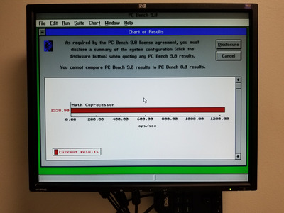
From cold it will boot and I can get a few benchmarks out of it, as I did with a couple of hand-picked simms from my collection, but after a minute or two you start getting odd behaviour; lockups, memory count errors at POST, I even had a bizarre experience where the wolf3d 286 benchmark routine started up with an entirely different demo!

I think we can safely say that this board just isn't happy running at 25MHz.

I would like to try some different oscillators between 80MHz and 100MHz (the board uses a /4 clock divider) to see just where the limit is... but they're fairly tricky (and expensive!) to track down, compared to those in the 40-50MHz range.

Wolfenstein runs at ~14.5-15fps at 20MHz and 19.8fps at 25MHz (but is unstable at the latter of course). If I could get a couple of megahertz increase on that 20MHz clock it should put me around 17fps, which is a nice speed for the game. Wing Commander is playable at 20MHz but would definitely be better with a few more clock cycles.

My collection database and technical wiki:
https://www.target-earth.net

Reply 179 of 180, by TimWolf

User metadata
Rank Member
Rank
Member

Hi guys. Glad to have found this thread. I just blew away my biostar mb1220ve bios while trying a new used io card from Ebay. Wish I'd have backed it up first. Got the bios you posted, thank you! Will have lots to add to the discussion when I get it it running.