VOGONS


First post, by jdgabard

User metadata
Rank Newbie
Rank
Newbie

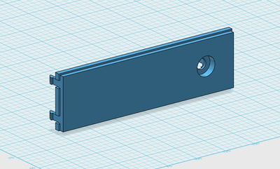
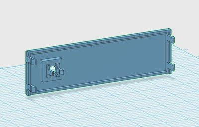
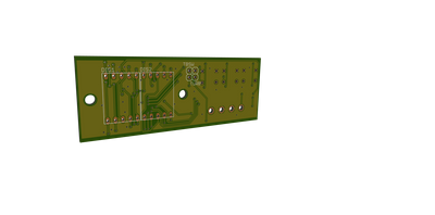
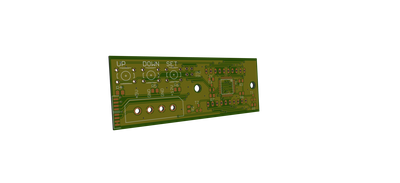
I do not have one on hand. So I cannot measure for myself. Does anyone have the dimensions of the MHZ displays, along with proper hole placements? I understand these are somewhat universal in their hole placement, and LED locations in later machines. I'm in the process of designing a replacement board. I have the basic schematic of it done, I just need to come up with a footprint for the board.

Any help would be appreciated.

Reply 2 of 9, by jdgabard

User metadata
Rank Newbie
Rank
Newbie
wiretap wrote on 2021-01-11, 02:05:

They vary from case to case. There is no universal size or hole placement. I have maybe 15 or so MHz displays, and all are different.

Ok, for some reason I thought they were somewhat universal. Thanks for the info.

Reply 3 of 9, by Sphere478

User metadata
Rank l33t++
Rank
l33t++

I would love to work with you on designing a bay insert for newer computers that adds a turbo button and mhz display along with key lock. Is that what you are trying to do?

I have ideas that may be of help. But little to no experience with 3d model building or gerber rendering. But I know some other people who may be able to help on those fronts.

Sphere's PCB projects.
-
Sphere’s socket 5/7 cpu collection.
-
SUCCESSFUL K6-2+ to K6-3+ Full Cache Enable Mod
-
Tyan S1564S to S1564D single to dual processor conversion (also s1563 and s1562)

Reply 4 of 9, by Sphere478

User metadata
Rank l33t++
Rank
l33t++

In general I think many of the displays were around 0.5” if I remember correctly. Also, many of them had a bunch of jumpers on them for programming the two displayed speeds. So what, three leads?

I think a modern version should be 888 not 188

Sphere's PCB projects.
-
Sphere’s socket 5/7 cpu collection.
-
SUCCESSFUL K6-2+ to K6-3+ Full Cache Enable Mod
-
Tyan S1564S to S1564D single to dual processor conversion (also s1563 and s1562)

Reply 5 of 9, by jdgabard

User metadata
Rank Newbie
Rank
Newbie

The bay insert is exactly what I had in mind. An easy way for people to convert ATX cases to fully support AT motherboards.

As for the design, I’ve pretty much have the board design done. Just need to tweak a few things. The design I’ve gone with is based on a Microcontroller. And would allow simple adjustment through a couple of tactile switches. I am planning on ordering a few boards in the next few weeks.

For the bay insert, I’ve got a basic design done. I just need to get the boards and a key-lock switch in to get the final dimensions. For the turbo switch I’m planning on going with a standard 8x8mm Lock switch with a 3d printed plunger. The cover is a snap in design.

I’ll post some photos in a bit.

Reply 6 of 9, by jdgabard

User metadata
Rank Newbie
Rank
Newbie

Here is what I have worked up so far.

Front.JPG
Filename
Front.JPG
File size
112.48 KiB
Views
488 views
File license
Fair use/fair dealing exception
Back.JPG
Filename
Back.JPG
File size
74.93 KiB
Views
488 views
File license
Fair use/fair dealing exception
pcb_front.png
Filename
pcb_front.png
File size
131.94 KiB
Views
488 views
File license
Fair use/fair dealing exception
pcb_back.png
Filename
pcb_back.png
File size
136.44 KiB
Views
488 views
File license
Fair use/fair dealing exception

Reply 7 of 9, by jdgabard

User metadata
Rank Newbie
Rank
Newbie
Sphere478 wrote on 2021-01-17, 08:20:

In general I think many of the displays were around 0.5” if I remember correctly. Also, many of them had a bunch of jumpers on them for programming the two displayed speeds. So what, three leads?

I think a modern version should be 888 not 188

If you have any input on the design, I'd be happy to hear it.

Reply 8 of 9, by Sphere478

User metadata
Rank l33t++
Rank
l33t++

Have you considered using a 3 digit Dc voltage meter on the 12v rail with a potentiometer run through a voltage stabilizing Device like a precision voltage reference? (Not sure if that’s how those things work) but you turn the dial to vary from 000 to 999

You could cut the display lead for the decimal.

Sphere's PCB projects.
-
Sphere’s socket 5/7 cpu collection.
-
SUCCESSFUL K6-2+ to K6-3+ Full Cache Enable Mod
-
Tyan S1564S to S1564D single to dual processor conversion (also s1563 and s1562)

Reply 9 of 9, by Sphere478

User metadata
Rank l33t++
Rank
l33t++

I think a very needed feature is a heavy duty AT power supply switch like a 1”x1” rocker. And to make it stable the insert should be a box that screws into at least the first four screws cause you’ll be pushing it all the time.

All these atx cases need power switches for these AT power supplies and even the adapters for atx power supplies do as well.

Sphere's PCB projects.
-
Sphere’s socket 5/7 cpu collection.
-
SUCCESSFUL K6-2+ to K6-3+ Full Cache Enable Mod
-
Tyan S1564S to S1564D single to dual processor conversion (also s1563 and s1562)