VOGONS


First post, by quicknick

User metadata
Rank Oldbie
Rank
Oldbie

I don't usually pick very damaged stuff, unless it's something really interesting/unique. Well, couldn't take my eyes off this (former) beauty, so I got it for very cheap.

SL-75FRN2-RL board.jpg
Filename
SL-75FRN2-RL board.jpg
File size
814.5 KiB
Views
1330 views
File license
Fair use/fair dealing exception

Fortunately the damage is very localized and vast areas of the board look brand new after the mandatory washing. Of course all 10 VRM caps (Sanyo and Nippon ChemiCon) are destroyed while the rest of generic junk are in perfect shape 😁.

SL-75FRN2-RL socket.jpg
Filename
SL-75FRN2-RL socket.jpg
File size
843.34 KiB
Views
1330 views
File license
Fair use/fair dealing exception

Most of the destroyed or missing parts are already sorted out and I will replace them tomorrow, but in the area between the CPU socket and the VRM caps there are three badly damaged SMD resistors. I've been able to determine the value of two of them, but the third is beyond any hope. I know it's not a very common board, but maybe someone here has it and can help me with a close-up of that area - I cannot thank you enough for that effort.

It seems that the "L" variant is much more common than this "RL", but from what I've seen the relevant area is identical.

Cheers!

Last edited by quicknick on 2022-10-03, 22:21. Edited 1 time in total.

Reply 2 of 22, by computerguy08

User metadata
Rank Member
Rank
Member

Given the brutal state of the PCB components (the CPU socket is literally ripped in half lmao), I would also carefully analyze the state of the traces in the damaged areas. Have you tried measuring that damaged SMD resistor ?

Reply 3 of 22, by quicknick

User metadata
Rank Oldbie
Rank
Oldbie

The inductors (and the socket) will be transplanted from a dead GA-7N400 Pro2 and hopefully they'll work. VRM stage is quite similar (HIP6602+6301 for the Gigabyte, HIP6602+6302 for the Soltek, difference being due to the number of phases, 3 vs 2).

An extremely nice chap that sells a similar board on a popular auction site helped me today with very detailed photos of the area, and the resistor in question is marked 103 (10kohm). Before that, I tried to measure the biggest piece (it was split in three), and after much hassle I got a reading of around 77k, so without the photos I would have been far off the value, fitting a 100k in there.

Traces look very good so far, but the final verdict will be after I remove all the socket remains. So off to work I am 😀

Reply 4 of 22, by bofh.fromhell

User metadata
Rank Oldbie
Rank
Oldbie

Somewhat OT.
But I'm guessing the inductors where pried of because they had copper visible on them.
And the rest of the damage is just the result of the crowbar or large pliers used.
If the board was bent at lot during this violation there's a chance the NB solder balls are cracked =/
If only the perpetrator knew that an undamaged board would be worth atleast 100x the metal value.

Reply 5 of 22, by quicknick

User metadata
Rank Oldbie
Rank
Oldbie

Yeah, not the first time I got stuff with inductors removed, I'm sure copper scavenging is the reason. Broken socket must be because of heatsink removal without unlatching it. Board isn't warped at all, but solder ball damage isn't out of the question.

A short while ago I suffered the first setback in my quest - the socket of the donor board is now destroyed. Used the hot air station but it wouldn't move. Heated it more, ended up bent like a banana because I had to attach a heatsink to the lugs or else no way to pull it out when the solder melted. And it was yellow, the perfect match for this board 🙁

I have another one, and started the tedious job of desoldering the pins one by one, so it might take a while.

Reply 6 of 22, by majestyk

User metadata
Rank Oldbie
Rank
Oldbie

yep - a decent desoldering station is highly recommended for this "socket job". And it still takes a while.

Since the upper / slider part has been torn off one can gently remove every single pin after desoldering it.

Reply 8 of 22, by computerguy08

User metadata
Rank Member
Rank
Member
quicknick wrote on 2021-01-24, 16:41:

A short while ago I suffered the first setback in my quest - the socket of the donor board is now destroyed. Used the hot air station but it wouldn't move. Heated it more, ended up bent like a banana because I had to attach a heatsink to the lugs or else no way to pull it out when the solder melted. And it was yellow, the perfect match for this board 🙁

I would have used a heat gun instead, much more thermal energy is transfered to the PCB than the desoldering station can output, thus making for a quick removal.
I tried this method with some donor socket A boards, all of the sockets survived the process.

Reply 9 of 22, by quicknick

User metadata
Rank Oldbie
Rank
Oldbie

I guess green will have to do:

SL-75FRN2-RL resocket.jpg
Filename
SL-75FRN2-RL resocket.jpg
File size
792.55 KiB
Views
1228 views
File license
Fair use/fair dealing exception

Not soldered yet, just laid over the destroyed one, for artistic impression.

Desoldering from the donor GA-7VA was much harder than I imagined, i had to use the hot air (on lowest setting) and vacuum desoldering stations simultaneously, otherwise the power and GND pins wouldn't clear. This socket also has a problem - it's missing the bit that retains the lever when you push it down, so it has the tendency to unlatch by itself. I'll have to think of something.
Tried the yellow top from the bent one but it doesn't quite fit, despite both being made by AMP there are minor differences.

Yeah, I guess a hot air gun would have worked (or maybe even a small blowtorch, as seen on Youtube), but I have bad memories of using it to remove a 85C206 PLCC chip with less than ideal results 😁 so I didn't consider using it for this project.

Reply 10 of 22, by Horun

User metadata
Rank l33t++
Rank
l33t++

Great work ! Looks good so far ! Have a 486 board/socket that has a latch with broken lock tab and found a Heat sink that extends over the lever so it can not pop open unless the HS is removed. Might work same on soc 7 if you find right heatsink. Just an idea ;p

Hate posting a reply and then have to edit it because it made no sense 😁 First computer was an IBM 3270 workstation with CGA monitor. Stuff: https://archive.org/details/@horun

Reply 11 of 22, by bofh.fromhell

User metadata
Rank Oldbie
Rank
Oldbie

Going by the pic it looks like the plastic tab to hold the lever is there on the socket.
Its just not aligned with the lever properly.
Could it be the wrong lever for the socket?
Tho a tiny mod to the lever should sort it.

Following this project closely.
Lets hope we get to see a runner eventually =)

Reply 12 of 22, by quicknick

User metadata
Rank Oldbie
Rank
Oldbie

Looking good:

SL-75FRN2-RL 1.jpg
Filename
SL-75FRN2-RL 1.jpg
File size
1.13 MiB
Views
1157 views
File license
Fair use/fair dealing exception
SL-75FRN2-RL 2.jpg
Filename
SL-75FRN2-RL 2.jpg
File size
1.34 MiB
Views
1157 views
File license
Fair use/fair dealing exception

But unfortunately, dead as a doornail. No beeps, POST card only shows dashes. Tried multiple CPUs, various RAM sticks or even no RAM at all, hoped for a corrupted BIOS so tried two other versions that I could find on the net, nothing. Vcore is spot on, the other VRM below the AGP slot that had one coil smashed is outputting 1.5V, went all over the board with a magnifier and couldn't find any more damaged SMDs or anything out of the ordinary. I tried to keep my expectations low, due to the initial state of this board, but still it's tough to admit defeat. I guess I'll frame this and hang it on my wall 😀

Reply 13 of 22, by majestyk

User metadata
Rank Oldbie
Rank
Oldbie

Is the CPU getting warm when you measure Vcore? If not maybe Vcore breaks down under load and the CPU is turned off.
I think there are 3 VRMs for the CPU. Do all of them work?
On some pictures on the net the right VRM inductor has only very few windings (about 4). and the magnetic core is larger.

inductors_soltek1.jpg
Filename
inductors_soltek1.jpg
File size
64.94 KiB
Views
1127 views
File license
Fair use/fair dealing exception

If the VRM circuit is unable to compensate this difference and the core voltage doesn´t match the nominal value exactly, the board probably won´t start up.
Like in the cases where capacitors deviate to much from their nominal values and the system doesn´t start up also.

Reply 14 of 22, by quicknick

User metadata
Rank Oldbie
Rank
Oldbie

CPU is getting warm, heatsink gets really hot if I unplug the fan. I said earlier that Vcore is spot on, well actually it's about 30mV higher than nominal (tried with 1.5 and 1.6V CPUs).
Your reply motivated me to investigate further, so I checked the datasheets of HIP6301 and HIP6302 (the PWM controllers of the donor Gigabyte board and of the Soltek board. Both have their switching frequency set by a resistor, and on both boards this is 150kohm resulting in a frequency of 200kHz, therefore I assume the inductors should be roughly compatible. They are almost identical to the originals on the Soltek (3 wires in parallel, 5 turns, green core).
The other inductor that you mentioned, near the Aux 12V connector, is actually located before the VRM stage (circled with green on the schematic below), and it is pulled from the same position from the donor board. I have very limited knowledge of the inner workings of the VRM, but from what I know this inductor isn't as critical as those on the output (circled red...ish).

Now, studying the datasheet I found out they both have a PGOOD pin:

HIP6302 datasheet wrote:

Power good. This pin provides a logic-high signal when the microprocessor CORE voltage (VSEN pin) is within specified limits and Soft-Start has timed out.

Measured it, was very close to zero volts. At this point my expectations were sky-high, I thought I was onto something. Next logical step was to measure the VSEN pin:

Power good monitor input. Connect to the microprocessor CORE voltage.

To my surprise, VSEN voltage was around 1.36V (Vcore being around 1.63V). Again from the datasheet, voltage on VSEN should be within 10% of what is requested through the VID pins, else PGOOD goes low.
The gold paint on this motherboard makes next to impossible to follow a trace, so I didn't waste much time trying to figure out where the voltage was 'lost', and directly connected Vcore to VSEN via a 100ohm resistor. With this mod in place the VSEN rose to about 1.6V, well within the 10% window, yet the PGOOD remained low.

Having no explanation for this I tried to make sure it isn't a case of something else on the board keeping the PGOOD low, but soon another surprise - nothing is connected to the corresponding pad. I even desoldered the controller to check if there isn't a trace going "inwards" from the pad, and indeed there isn't one. The Soltek board doesn't make use of the PGOOD signal from the PWM controller. Still, this doesn't explain why the PGOOD remains low even with VSEN brought to (almost full) Vcore.

Finally, here's the schematic. Oh how I wish I had the Soltek one, but it seems impossible to find. Instead, here's the VRM stage of the MSI KT4V which uses the same chips as the Soltek (HIP6302 PWM controller, HIP6602 MOSFET driver), major difference being the input voltage (the MSI powers the CPU from the 5V rail whereas the Soltek uses 12V instead). Other than that, the MSI really use the PGOOD signal from the controller, and here's the shock for me - the presence of R53/R69, a divider that is consistent with the VSEN drop that I measured on the Soltek board. This baffled me, because it means the voltage on VSEN can never be within 10% of the programmed voltage, so at this point I think either there's a mistake in the datasheet or I'm reading it very wrong...

msivrm.png
Filename
msivrm.png
File size
171.95 KiB
Views
1103 views
File license
Public domain

Reply 15 of 22, by eebenz

User metadata
Rank Newbie
Rank
Newbie

Hi!

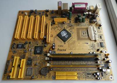
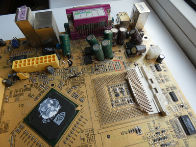
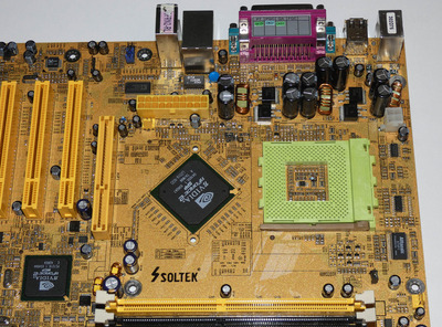
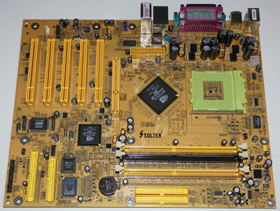
Have read this forum for some time, now registered. I'm also repairing an Soltek board (SL65DVB, Pentium III 1ghz) which I bought with caps very bulged. After buying it I was told that someone had already tried to change a few of them... The changed ones were six caps in VRM sections which were replaced with some very cheap looking ones. Solderwork was awful. I replaced them with panasonic fm's. Also changed other caps (many of them were also bulging) with salvaged but known to work low esr caps. The physically smallest ones I kept unchanged though, they all look good.

Also reflashed the bios as it had bios for different chipset. Learned a lot about eeprom chips as I didn't have a proper programmer, only 3com network card with address lines enough for 128kb chips. With linux split command, modding the software and adding switch to manually switch between the upper and lower 128k of 256k eeprom, I managed to successfully program it 😀

But back to the subject, the motherboard is still not working. Tried different cpu's and power supplies and whatever. Why I'm posting this to your thread is because it's behaving exactly as your board. No beeps etc. just fans spinning and cpu heating up. And today I started measuring the VRM section inspired by your post. I'm currently using my non-retro PC's PSU, 750W Evga Gold to have as accurate voltages as possible.

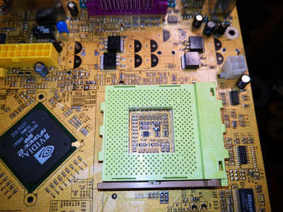
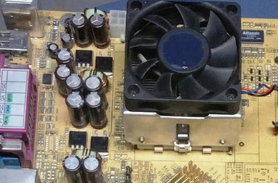
Theres three big mosfets on the board, two of them in VRM section. I measured voltages on those mosftes backplates against GND: 3.30V, 4,98V and 1.76V which I guess is Vcore.

In my board there's only one HIP ic, HIP6018BCB. I measured it and just like in your board VSEN is lower than Vcore, 1.40V. PGOOD is obviously low and FAULT pin which is used to indicate only overvoltage&overcurrent is low as it should be. What I can see through the legs of the component (for some pins traces are under the component) PGOOD and FAULT are also not connected to anywhere on to board... The voltages might be monitored by some other ic. If this behavior that VSEN is about 35mV lower than Vcore, so much that PGOOD goes down, is not some Solteks weird design by purpose, then I guess we have same problem with our mobos 😀

When I change the CPU to Celeron 500MHZ with recommended Vcore voltage around 2,00V, the Vcore also changes. VSEN stays at 1,60V. So the voltage identification system at least works. https://en.wikipedia.org/wiki/Voltage_regulat … _identification

Have you connected LED's to your mobo, what they show? For me after powering the board up:
-POWER LED lights up
-HDD led lights up, if a hdd with power cable is connected (i guess the led pin is just connected in pcb to the isa connector directly...)
-SUSPEND led blinks. Shouldn't a suspend led be off when your computer is running?! The suspend led is connected to a NE555 timer which generates the blink and it's not particulary fast or slow, just a regular suspend blink what you can see on various electronic devices. I haven't yet managed to find which component controls the NE555. But anyways I guess this blink is caused by the weird voltages in the HIP ic / VRM section. I don't fully understand yet how that voltage regulation and HIP ic works, but I guess the voltages are monitored by some other chip. And that chip puts the led blinking because voltages don't match.

I'll post more when I continue investigating the problem.

-eebenz

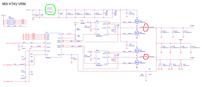
EDIT: I managed to find schematics for Soltek 65KV. Page 17 is the VRM and HIP chip. Cross on pins means they are not connected/used. Fault, pgood and rt have those crosses. In my mobo, the 555 timer circuit which blinks the suspend button is reseted by south bridge. Now it's not reseting it. I'll read that schematic more some other day, I'll go to sleep now. Heres a link to the schematic, I hope it's okay to post it here: https://www21.zippyshare.com/v/VAMqLvSl/file.html

Reply 16 of 22, by _tk

User metadata
Rank Newbie
Rank
Newbie
effy wrote on 2021-01-24, 18:07:

Good luck. Old Soltek boards are definitely worthy of being saved.

I don't remember much about Soltek back in the day, but somehow I acquired one ~20 years ago and it's a decent looking 440BX board of theirs.

Is it worth keeping and using?

Reply 17 of 22, by quicknick

User metadata
Rank Oldbie
Rank
Oldbie

Hi eebenz, and welcome to the forums!
No I haven't connected any LEDs to the board's headers, but I think it's a very good idea as it might provide some clues. Will look into it when I'll revisit the board, which is now stored in the "dead" box along with an equally deceased GA-7VTXH+. I feel that I spent a bit too much time on those, and need to focus on some other projects to clear my head.

Interesting fact that they did not use the PGOOD and FAULT pins, maybe the operation of the Vcore VRM is not monitored at all. Since you have the schematic, you should identify and measure all the minor rails and ensure they are in spec (I was surprised at their number on the MSI KT4V, and the schematic allowed me to fix a short between the +3v3 and the 3VDUAL rail, whatever that is).

And speaking of schematics, since I was unable to find one for any Soltek board but you managed for yours, could you please check if one for my board is available? Thank you.

Reply 18 of 22, by eebenz

User metadata
Rank Newbie
Rank
Newbie

Hi eebenz, and welcome to the forums!

Thanks!

>I feel that I spent a bit too much time on those, and need to focus on some other projects to clear my head

Same feeling here. Yesterday I fixed one trace damaged by cpu cooler socket but it didn't help. I have noticed that damage earlier but haven't fixed it because the damaged trace was just a data line between sdram sockets (pin 75) and northbridge. Also the other traces near the broken one were datalines too. As excepted fixing it didn't help anything. Otherwise the board is physically in mint condition and shorting data lines should not burn anything.

>I was surprised at their number on the MSI KT4V, and the schematic allowed me to fix a short between the +3v3 and the 3VDUAL rail, whatever that is

Where that short was located? On ic pins or somewhere else? On my board theres small tinned sections for probing in the thinnest lines. They are pretty neat for probing but there might be short somewhere too....

>And speaking of schematics, since I was unable to find one for any Soltek board but you managed for yours, could you please check if one for my board is available? Thank you.

It's not excatly same as mine but similar. I found the schematic just using google image search when I searched for soltek schematics. That was the only soltek schema I found though.

Reply 19 of 22, by effy

User metadata
Rank Newbie
Rank
Newbie
_tk wrote on 2021-02-08, 23:55:
effy wrote on 2021-01-24, 18:07:

Good luck. Old Soltek boards are definitely worthy of being saved.

I don't remember much about Soltek back in the day, but somehow I acquired one ~20 years ago and it's a decent looking 440BX board of theirs.

Is it worth keeping and using?

They were good solid "no-name" boards back in the slot1/s370 days, when people were concentrated on Abit, Asus, Gigabyte. Kinda like DFI and AOpen, maybe EpoX too. Soltek really came into their own in the Athlon XP days. Usually had some cool different color combos as well.