VOGONS


Reply 20 of 45, by weedeewee

User metadata
Rank l33t
Rank
l33t

Just thought of the extra 8 dip 20's you have...

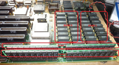
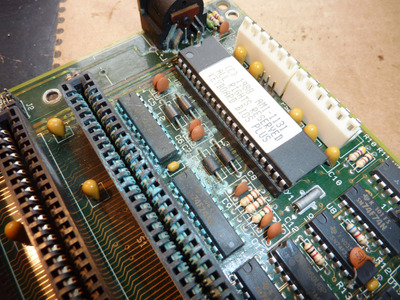
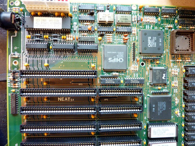
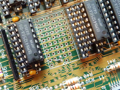
they are also present on the neat-sx board, but they are part of bank0 and 1, just look at the image file.php?id=106838&mode=view
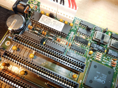
the top row of sockets are a combined dip18 & dip 16, the following two rows are combined dip 20 & dip18 & dip 16.
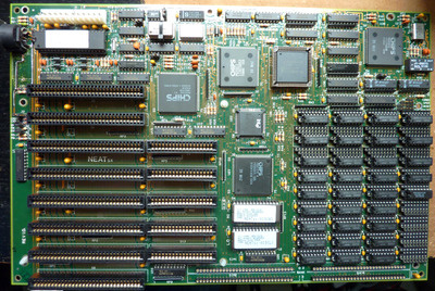
That would mean that to use the 8 separate dip20 sockets on your board, you would have to remove all 36 chips ,
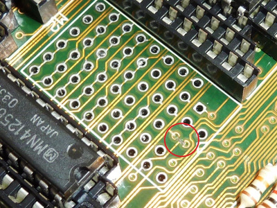
( and Maybe you'll have to find out which of those sockets is there for the parity bit
and place a 1Mbit chip in the four sockets that are responsible for the parity bit. If you're using the dip20 sockets with 256K @4bit each, since I doubt a 512Kbit chip exists. )
I'm not quite sure of this though since the memory layout for the neat-sx shows the use of 256Kbit chips as not requiring any parity chips... Which I think is wrong, but I can't test it since I lack the chips :-p
https://th99.bl4ckb0x.de/m/E-H/31760.htm
http://www.win3x.org/uh19/motherboard/show/2100

Also the microhouse layout for the neat-sx is a bit off since it shows 10 rows of sockets, while only 9 rows of combined sockets are actually present .

Right to repair is fundamental. You own it, you're allowed to fix it.
How To Ask Questions The Smart Way
Do not ask Why !
https://www.vogonswiki.com/index.php/Serial_port

Reply 21 of 45, by majestyk

User metadata
Rank Oldbie
Rank
Oldbie

In the meantime I finished the restauration work. The backside had to be cleaned entirely, hundreds of pins had been bent and some resoldering was done also.
Finally the four missing ferrite inductors (keyboard connector EMC) that were completely corroded got replaced by brandnew Murata 7A inductors.

neatsx16.JPG
Filename
neatsx16.JPG
File size
1.6 MiB
Views
980 views
File license
Fair use/fair dealing exception

I also ordered a couple of DIP-RAM chips and hope to find some 30pin 1MB SIMMS in my attic so the memory configuration can be investigated further.
It´s a very nice, clean and shiny mainboard now, gone are the dirt, the corrosion, the stench and you hardly notice any signs of it´s cruel past.

Reply 22 of 45, by Schule04

User metadata
Rank Member
Rank
Member

Small update: the jumper next to the front panel headers is not for turbo on or off like I assumed, it's for disabling the on board DIPP RAM. With it unplugged the 2 SIMMs are recognized as 640KB+1024KB.

@majestyk: Very nice restoration work. How long do those supercaps hold their charge?

Reply 23 of 45, by Schule04

User metadata
Rank Member
Rank
Member

Another update: weedeewee was right, the 8 empty sockets were for an alternative memory population. After removing all the 256K and 64K DIPPs the board started to recognize the 256Kx4 chips I put there properly as 1MB, and together with the SIMMs the board now reports 5MB total (of which 640KB + 4096KB is usable). Enabling 0 waitstates also seems to work without issues now.

I installed Windows 95 just to see how it would run, and honestly it's not as bad as I expected. Certainly seems like it would have been usable for basic tasks back then.

The standard pin headers I ordered do not fit into the holes of the motherboard, they are too thick.

Reply 24 of 45, by majestyk

User metadata
Rank Oldbie
Rank
Oldbie

Hi there,

as for the supercaps: A 4F 5.5V supercap holds the settings for about 1 to several weeks. It depends on the power consumption of the RTC and other components like the CMOS RAM itself.

I have been experimenting with RAM sizes as well. Now the board runs with ....snare roll.........8 MB!
To achieve this Jumper JP6 must be set to "1-2".
Then all 36 onboard sockets have to be populated with 1MB x 1 Chips (like 411000 or 511000). Onboard RAM is detected correctly by BIOS.

Then I soldered 30-pin 2.54 mm connectors to 4 regular 1MB SIMMS (9-chip) and put them in the SIPP sockets.

neatsx17.JPG
Filename
neatsx17.JPG
File size
206.23 KiB
Views
926 views
File license
Fair use/fair dealing exception

These are NOT detected automatically by BIOS. You have to edit the respective registers for the MHC (82C812) to enable them and set the size of the memory chips like this:

neatsx18.JPG
Filename
neatsx18.JPG
File size
163.39 KiB
Views
926 views
File license
Fair use/fair dealing exception
neatsx19.JPG
Filename
neatsx19.JPG
File size
182.59 KiB
Views
926 views
File license
Fair use/fair dealing exception

As y0u can see I re-set the RAM timing to "1 wait state" for now, because during the memory test of "speedsys" the machine crashes with "parity error, system halted" when testing the SIPP RAMS. The onboard chips run perfectly with "0 wait states".

Reply 25 of 45, by majestyk

User metadata
Rank Oldbie
Rank
Oldbie

In the meantime I was able to acquire a second NEATsx, the 20 MHz version this time, it´s not been exposed to violence as far as I can see, but it´s a VARTA victim as well.

neatsx50.JPG
Filename
neatsx50.JPG
File size
1.75 MiB
Views
915 views
File license
Fair use/fair dealing exception

So first of all some components had to be removed:

neatsx51.JPG
Filename
neatsx51.JPG
File size
1.71 MiB
Views
912 views
File license
Fair use/fair dealing exception
Last edited by majestyk on 2021-04-09, 18:08. Edited 1 time in total.

Reply 26 of 45, by weedeewee

User metadata
Rank l33t
Rank
l33t

I got to ask, How long does it take you and what tools do you use to remove all those components ?

Right to repair is fundamental. You own it, you're allowed to fix it.
How To Ask Questions The Smart Way
Do not ask Why !
https://www.vogonswiki.com/index.php/Serial_port

Reply 27 of 45, by majestyk

User metadata
Rank Oldbie
Rank
Oldbie

This is basically a job for my trusty ZD-915 desoldering station. Still in cases like this it takes about 2-3 hours to remove the components since one has to proceed with caution.
After that everything needs to be cleaned and the corrosion must be removed carefully. The result should look like this:

neatsx52.JPG
Filename
neatsx52.JPG
File size
1.56 MiB
Views
895 views
File license
Fair use/fair dealing exception

Then a lot of good flux has to be applied and the traces can get a nice tin coating:

neatsx53.JPG
Filename
neatsx53.JPG
File size
254.1 KiB
Views
895 views
File license
Fair use/fair dealing exception

Everything has to be cleaned again, the solder points that have filled with solder must be desoldered again from the backside.
In most cases lots of interruptions that have been caused by the battery leakage need to be repaired with thin wires. All traces must be checked carefully and measured.
Then the new components can be put in thei places. I don´t reuse any of the corroded old components.

neatsx54.JPG
Filename
neatsx54.JPG
File size
1.53 MiB
Views
891 views
File license
Fair use/fair dealing exception

And it´s working again.

neatsx55.JPG
Filename
neatsx55.JPG
File size
1.79 MiB
Views
890 views
File license
Fair use/fair dealing exception

The last ISA slot is still missing so it´s easier to make additional measurings in case anything goes wrong.

Now I have done some testing and there are some interesting findings:

1. This 20 MHz NEATsx has a later BIOS version "013" from 1991.
2. It autodetects RAM sticks in the 4 SIPP slots correctly, so there´s no need to edit the MCH´s registers.
3. It enables memory interleave automatically as soon as an even number of banks are populated.
4. The parity error when testing SIPP RAM at "0 wait states" does not occur here (with the same RAM sticks).
5. There´s an additional ceramic capacitor (50 pF) between pins 7 and 8 of U9 (SN74F32N) that is not to be found on the 16 MHz version.

Reply 28 of 45, by majestyk

User metadata
Rank Oldbie
Rank
Oldbie

Here´s the sequel:
This week I found a third 20 MHz NEATsx in excellent condition and with near to no battery damage.
The happiness didn´t last long. After cleaning everything, checking all traces and contacts and removing the usual shorted tantalum capacitors in the +12V and -12V lines, I expected this one to work "out of the box".
The very moment the mainboard is powered up the speaker starts beeping 3 x short repeatedly ad infinitum:
beep-beep-beep......beep-beep-beep...... beep-beep-beep.....beep-beep-beep............
Needless to say there´s no video output, no POST...

I remember that AMI BIOSes indicate memory issues with 3 beeps, but as far as I recall that´s just 3 beeps once.
I wonder if anybody has experienced this permanent beeping before?

Reply 29 of 45, by Deunan

User metadata
Rank Oldbie
Rank
Oldbie
majestyk wrote on 2021-04-15, 18:26:

I remember that AMI BIOSes indicate memory issues with 3 beeps, but as far as I recall that´s just 3 beeps once.

I'm impressed, I consider mobos with that much spill damage to be too far gone for repair. I guess a proper desoldering station does help a lot, though how do you deal with those corroded solder point that just won't flow at all? I know adding more fresh solder helps (and plenty of flux) but in the past I had corrosion that would not even work with that. You'd sooner rip a via out than actually desolder it - so I'm curious about your technique.

As for the beeps, I can't remember now (and the beeps are not consistent between BIOSes or even mobos/versions) so a POST card would code would be more helpful. Without one I'd start randomly swapping the RAM chips in hopes that only one or two are bad and I'd get past the first 64k error with just moving them around.

Reply 30 of 45, by dataino.it

User metadata
Rank Member
Rank
Member

Great job !!
Great restoration

I have similar mobo with no bios

can u dump it?

Attachments

  • neat.jpg
    Filename
    neat.jpg
    File size
    1.1 MiB
    Views
    855 views
    File license
    Public domain

Reply 31 of 45, by Schule04

User metadata
Rank Member
Rank
Member
dataino.it wrote on 2021-04-15, 20:47:
Great job !! Great restoration […]
Show full quote

Great job !!
Great restoration

I have similar mobo with no bios

can u dump it?

Thy this bios dump: Re: 80386 BIOS image collection

majestyk wrote on 2021-04-15, 18:26:
Here´s the sequel: This week I found a third 20 MHz NEATsx in excellent condition and with near to no battery damage. The happ […]
Show full quote

Here´s the sequel:
This week I found a third 20 MHz NEATsx in excellent condition and with near to no battery damage.
The happiness didn´t last long. After cleaning everything, checking all traces and contacts and removing the usual shorted tantalum capacitors in the +12V and -12V lines, I expected this one to work "out of the box".
The very moment the mainboard is powered up the speaker starts beeping 3 x short repeatedly ad infinitum:
beep-beep-beep......beep-beep-beep...... beep-beep-beep.....beep-beep-beep............
Needless to say there´s no video output, no POST...

I remember that AMI BIOSes indicate memory issues with 3 beeps, but as far as I recall that´s just 3 beeps once.
I wonder if anybody has experienced this permanent beeping before?

My board behaves like that when the memory is not populated or configured correctly. Did you try swapping out the RAM chips with one of the other boards?

Reply 32 of 45, by majestyk

User metadata
Rank Oldbie
Rank
Oldbie

Thanks to everyone for the suggestions - and compliments!
This brought me back to looking for a (base) memory issue. I had tested with 3 different sets of RAM, all known good. So I could rule out the RAM chips.
Then I inspected the mainbord around the RAM sockets very very carefully focusing on the upper sockets, since I assumed that base mamory would probably be at the beginning of the array.
Finally there was some strange mark to be seen besides the 2nd socket that could have been caused by a slipped screwdriver. Some people are known to use immense force when taking out some tine chip...
Could this be the reason for all the trouble?

neatsx58.JPG
Filename
neatsx58.JPG
File size
596.02 KiB
Views
830 views
File license
Fair use/fair dealing exception

Like it or not, the whole socket with it´s 6 rows of contacts had to be removed for any further investigations.

neatsx59.JPG
Filename
neatsx59.JPG
File size
272.54 KiB
Views
830 views
File license
Fair use/fair dealing exception

Ohhhh...kaaay, at least one trace cut!

I swiftly repaired this with 2 thin wires:

neatsx60.JPG
Filename
neatsx60.JPG
File size
597 KiB
Views
830 views
File license
Fair use/fair dealing exception

Then I put the socket back in, switched the whole thing on and BANG! it´s working flawlessly.

I will dump the BIOS later - it´s the improved version 13 as opposed to version 12 in the "386 BIOS" thread.

Last edited by majestyk on 2021-04-16, 18:44. Edited 2 times in total.

Reply 34 of 45, by majestyk

User metadata
Rank Oldbie
Rank
Oldbie

In the meantime - here are the 2 BIOS files for Elitegroup NEATsx version 13 for "dataino.it" and everyone who can use them:

Filename
NEATSX_v13_BIOS.7z
File size
35.63 KiB
Downloads
44 downloads
File license
Fair use/fair dealing exception

And the finished product (except for the battery):

NEATsx_61.JPG
Filename
NEATsx_61.JPG
File size
1.6 MiB
Views
799 views
File license
Fair use/fair dealing exception

Reply 35 of 45, by Deksor

User metadata
Rank l33t
Rank
l33t

This is great ! I have one board like this, heavily corroded. It gives me some hope I can fix it but I don't know if I have the time for that ...

By the way your BIOS matches the BIOS we have on uh19 (version 1.2).

What's the POST string of that BIOS ? I can't extract it from this ROM and I can't get any emulator to run it either.

Trying to identify old hardware ? Visit The retro web - Project's thread The Retro Web project - a stason.org/TH99 alternative

Reply 36 of 45, by Deksor

User metadata
Rank l33t
Rank
l33t

Allright I started to try to restore mine :
First I desoldered the same components :
zPmmbGbl.jpg

There was also a patch of corrosion on the backside for some reason (perhaps the board had been stored against another board with a varta battery ?)
1vieBC9l.jpg

Here's the area after the cleanup
nobt9DRl.jpg?1

Unfortunately, the solder mask seems to be more damaged than yours, it feels rough to the touch

I've started tinning the traces, which created lots of ugly flux residue. I'll have to clean that up as well.

Trying to identify old hardware ? Visit The retro web - Project's thread The Retro Web project - a stason.org/TH99 alternative

Reply 37 of 45, by majestyk

User metadata
Rank Oldbie
Rank
Oldbie

The NEATsx is a high build quality mainboard that has it´s advantages when repairing it. The copper traces are quite thick and the smaller traces don´t come off when soldering at higher temperatures. It´s due to the high pcb quality that these boards have even survived the VARTA attacks.

What did you use for removing the corrosion and the surface coating? I used a 5mm glass-fiber pen with fine fibers for that. It takes quite a while and you need a couple of replacement tips.

Today i equipped the third NEATsx with a holder for a CR2032 lithium cell. To have some space for the Schottky-diode and to make sure the pcb will never be polluted again, I put a small block of solid rubber between pcb and holder. Now we will see how long this coincell will last...

NEATsx_batt.JPG
Filename
NEATsx_batt.JPG
File size
853.58 KiB
Views
740 views
File license
Fair use/fair dealing exception

Reply 38 of 45, by Deksor

User metadata
Rank l33t
Rank
l33t

I used simply vinegar then isopropylic alcohol then water, I lost my glass fiber pen :'(

Trying to identify old hardware ? Visit The retro web - Project's thread The Retro Web project - a stason.org/TH99 alternative