Reply 20 of 40, by Deunan
Rank
Oldbie
Well, it could be dead. I highly recommend those "EPROM emulators" chips for experimenting with BIOS images, saves a lot of time.
Well, it could be dead. I highly recommend those "EPROM emulators" chips for experimenting with BIOS images, saves a lot of time.
My M321 is running on Winbond W27C512 chip having MR-BIOS on it. 😀
And i was able to also read the original BIOS ROM as 27C512.
(My journey is pretty much summed up here: Chipset datasheet for M321 (PC Chips) [Found chipset! OPTi 82C391] )
"640K ought to be enough for anybody." - And i intend to get every last bit out of it even after loading every damn driver!
GigAHerZ wrote on 2021-04-18, 18:28:My M321 is running on Winbond W27C512 chip having MR-BIOS on it. 😀
And i was able to also read the original BIOS ROM as 27C512.(My journey is pretty much summed up here: Chipset datasheet for M321 (PC Chips) [Found chipset! OPTi 82C391] )
So there's definitely something wrong with my ROM then; it won't read at all. I'm definitely interested in trying the MR BIOS and will give it a go when those eeproms arrive.
My collection database and technical wiki:
https://www.target-earth.net
hope you wake it up eventually.
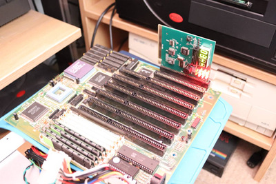
this is one of the finest classic 386 boards.
the chipset is one of the fastest clock-to-clock ones, but does not overclock very well.
if the board starts ticking, you may consider swapping the clock gen with crystal oscillator. so far all pcb versions i have seen have through holes and witing for them (not clear from the pictures you shared here).
this way you can get it past the 40mhz.
No change with a newly programmed W27C512 eeprom and a PC-CHIPS M321 BIOS image (v. 060692) from UH19:
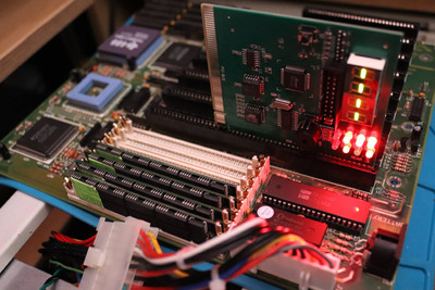
Edit: Same result with the v. 070791 BIOS image.
My collection database and technical wiki:
https://www.target-earth.net
Now, this is interesting.....
That's error code 03-- (according to the MR BIOS code list, that's a BIOS checksum error.. but at least it's evidence of something working).
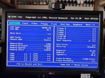
This is with a MR BIOS 1.30 linked to from above - underneath it all the M321 uses a rebadged Opti 82C391 chipset, so something is definitely working at least to a certain degree... but not with an original PC-CHIPS AMI BIOS.
My collection database and technical wiki:
https://www.target-earth.net
Maybe it's a "simple" case of some data or address line from bios rom to chipset being broken?
"640K ought to be enough for anybody." - And i intend to get every last bit out of it even after loading every damn driver!
megatron-uk wrote on 2021-04-20, 12:02:That's error code 03-- (according to the MR BIOS code list, that's a BIOS checksum error.. but at least it's evidence of something working).
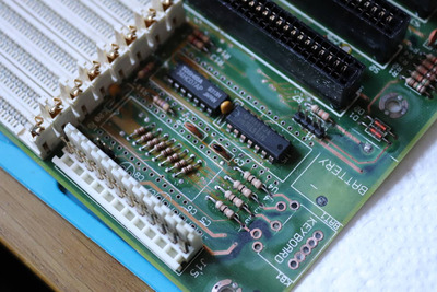
There was battery corrosion next to BIOS area, correct? Check all the address pins - BIOS should sit on the same bus as ISA so it's probably easiest to compare with one of the slots. I doubt it's the data lines, it would probably not boot at all to even show that 03 code in that case, but check that too. Data bus however can be isolated by a '245 nearby, or (on newer chipsets) same as ISA and connected to the 82C206 chip variant.
It's also a good idea to test first vs last ISA slot, since the signals can be routed to those somewhere in the middle and sometimes the spill disables parts of the mobo but not all of it, which is hard to find unless you do these sanity checks.
I admire your perseverence! Do you mind me asking where you got the keyboard socket? The one on my motherboard is leaning at a worrying angle and I'd like to have a spare in case it ever gives up the ghost.
Modern PC: i7-9700KF, 16GB memory, RTX 3060. Proper PC: Pentium 200 MMX, 128MB EDO memory, GeForce2 MX(200).
My understanding at this point is that the processor is running, and has started to execute the self-test routine from ROM, writing the results to IO port 80h. So I'm pleased to see that at least the board is now resurrected enough to do that.
I did desolder the original OTP BIOS chip and cleaned under it - there was very little evidence of corrosion around it (the closest obvious damage being one main trace from the AT header and a trace from the keyboard port), but I did fit a socket in its place - I should probably triple check the soldering of that again.
My collection database and technical wiki:
https://www.target-earth.net
Woody72 wrote on 2021-04-20, 12:26:I admire your perseverence! Do you mind me asking where you got the keyboard socket? The one on my motherboard is leaning at a worrying angle and I'd like to have a spare in case it ever gives up the ghost.
Sure - it was a pack (of 10?), pretty cheap, from one of those Chinese drop shipping sellers on Ebay:
https://www.ebay.co.uk/itm/10Pcs-Set-PCB-Pane … Nt/193878237014
One thing I had to do was bend the two metal shield support tabs on the front to fit the AT keyboard spacing on the motherboard. All the socket pins line up perfectly, it's just those non-transmitting tabs that don't quite fit - just bend them up to be flush, and then bend the tip back down again to suit the slightly different spacing, depending on your motherboard.
My collection database and technical wiki:
https://www.target-earth.net
I re-touched the each of the pins on the new BIOS socket as well as the two jumper wires I soldered at the cache sockets:
https://www.youtube.com/watch?v=s0iVc30RQg0
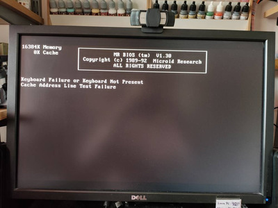
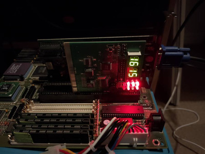
POST error codes galore!
😁
.
.
.
.
.
.
.
pushing my luck, I popped in a VGA card, and.....
.
.
.
.
.
.
.
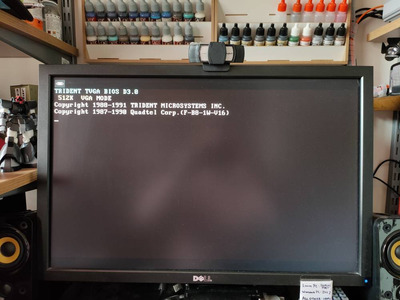
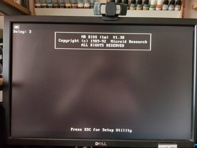
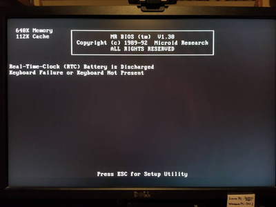
IT'S ALIVE! ALIVE, I TELL YOU! 😁
I know the keyboard controller on my board won't work with the MR BIOS ROM, as documented elsewhere, so the keyboard error I was expecting. Also, there's some rubbish information on the MR BIOS info screen - cache size is wrong (and the error probably indicates my jumper wires are not working), etc. But, the damn thing now actually works!
My score is now 1 out of 3 for the pile of scrap electronics I bought from Russia for just a couple £/$ each 😁
My collection database and technical wiki:
https://www.target-earth.net
Amazing! Congratulations!
"640K ought to be enough for anybody." - And i intend to get every last bit out of it even after loading every damn driver!
That's awesome you got it working!!!!
Fortes Fortuna Adiuvat!
A little more work and we have two new error codes, but some progress on the cache front:
According to the MR BIOS codes, they are, unsurprisingly:
- 15h: Keyboard controller failure - I've tested a 'JetKey' which I had spare, but it's no good either, so I'll probably need to pick up an Amikey or similar
- 16h: Size and test CPU cache
Regardless of whether I fit 128k of 256k or jumper for either, it only 'detects' 112k (which is an improvement on the 'Cache address line' failure I had previously). I've redone the two jumper wires and rechecked continuity, but it's got to be something related to that damage which is causing the cache errors.
My collection database and technical wiki:
https://www.target-earth.net
This a great progress. Was there any corrosion damage around the cache sockets or the cache chips themselves?
chrismeyer6 wrote on 2021-04-20, 19:48:This a great progress. Was there any corrosion damage around the cache sockets or the cache chips themselves?
No, no corrosion at that end of the board at all - it was limited to just a small area immediately surrounding the battery and keyboard socket. There were scratched traces on the underside of the board where the cache sockets are; I'm positive that this is the cause of the "cache detect/sizing" error. I'll admit that the size of those traces are at the limit of my what I can do by eye any more!
It probably needs a double and triple check.
My collection database and technical wiki:
https://www.target-earth.net
Yeah some of those super thin traces are hard to fully see without good magnifying goggles
Not really progressed any further with this. I did receive a couple of NOS Amikey-2 controllers, but they don't appear to make any difference to the "Keyboard controller failure or keyboard not present" error; I do see the keyboard lights flash on start, so there's power getting there, but I've tried the following controllers and they don't make any difference:
- Regional (as fitted originally to this board)
- JetKey (from a working 286)
- Amikey-2 (two, NOS parts)
In the meantime I'll have to do something about that cache error. I'll try removing those jumper wires and just soldering on the shortest wire links I can get away with.
My collection database and technical wiki:
https://www.target-earth.net