VOGONS


First post, by figbash

User metadata
Rank Newbie
Rank
Newbie

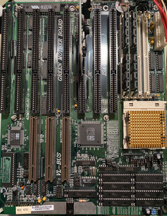
Hey guys, I recently got an EFA 4DMS=HL3G board that I'm planning to build an Intel DX4-100 with.
The issue is I cannot get it to POST, there is no video signal or beep after powering it. The keyboard lights will flash once, the CPU will get warm.
Visually I think it looks great, I don't see any damaged traces or corrosion or bloated caps. It used a coin cell battery and there was no damage from that. I am by no means an expert on any of this though.

Things I have tried:
1. Got a new CMOS battery even though the old one was showing 3V
2. Pulled CMOS battery, set reset CMOS jumper for 5 mins, left unplugged for 24 hours to clear
3. When I got it it didn't have the L2 cache populated, so I bought some from Mouser and installed it
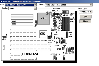
4. I found the correct jumpers using an old EXE EFA created I found on the wayback machine, jumpers seem to be correct
5. I tried 2 different PSUs, both of which work with other machines
6. I've tried 2 different CPUs, an AMD DX4-100 and the Intel DX4-100. Unknown if either have any issues as this is my only 486 board, but they both get warm at least
7. Tried without RAM, with 1 RAM stick, with 2 RAM sticks. No beep.
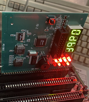
8. Bought a POST test card, it says 0D. This uses Award BIOS 4.5, and looking online this code seems to be "Initialise video interface; Detect CPU Clock. Read CMOS location 14h to find out type of video. Detect and initialise video adapter." The POST card does not beep. Pulling the memory changes the POST code to C1. Pulling the cache does not effect it.
9. Since it was talking about initing the video adapter, I tried an ISA video card I know works, and also a VESA video card.
10. Pulled the BIOS and scraped all the legs (Didn't see any corrosion though)
11. Went outside and screamed at the clouds

Is anyone familiar with this board, or have anything else I could try?

Attachments

Reply 1 of 44, by Deunan

User metadata
Rank Oldbie
Rank
Oldbie

The buzzer on that POST card need to be connected to mobo SPEAKER output. That's what that 2-pin connector next to the buzzer is for. You won't get any beeps otherwise.
Some of these 486 mobos are really picky about RAM sticks. Do try the other bank, and possibly other RAM sticks if you have them.

Reply 2 of 44, by Horun

User metadata
Rank l33t++
Rank
l33t++

If you have a digital voltmeter check the voltage on the screw (or center lead) of Q4 to ground, it should be 3.3v. If not then it is not regulating voltage properly. Try a 5v 486 and see what happens.

Hate posting a reply and then have to edit it because it made no sense 😁 First computer was an IBM 3270 workstation with CGA monitor. Stuff: https://archive.org/details/@horun

Reply 3 of 44, by figbash

User metadata
Rank Newbie
Rank
Newbie
Deunan wrote on 2021-04-17, 22:55:

The buzzer on that POST card need to be connected to mobo SPEAKER output. That's what that 2-pin connector next to the buzzer is for. You won't get any beeps otherwise.
Some of these 486 mobos are really picky about RAM sticks. Do try the other bank, and possibly other RAM sticks if you have them.

Oh alright. I had my speaker connected when testing so it still isn’t beeping.
I’ve tried 3 different sets of ram sticks I have, and in multiple banks, doesn’t seem to make a difference though.

Reply 4 of 44, by figbash

User metadata
Rank Newbie
Rank
Newbie
Horun wrote on 2021-04-18, 00:40:

If you have a digital voltmeter check the voltage on the screw (or center lead) of Q4 to ground, it should be 3.3v. If not then it is not regulating voltage properly. Try a 5v 486 and see what happens.

I have a multimeter, sorry what do you mean by Q4?

Reply 5 of 44, by paradigital

User metadata
Rank Oldbie
Rank
Oldbie
figbash wrote on 2021-04-18, 02:23:
Horun wrote on 2021-04-18, 00:40:

If you have a digital voltmeter check the voltage on the screw (or center lead) of Q4 to ground, it should be 3.3v. If not then it is not regulating voltage properly. Try a 5v 486 and see what happens.

I have a multimeter, sorry what do you mean by Q4?

He means the lone transistor at the edge of the motherboard, directly south (in the orientation of your photo) of the right-most VLB slot. It’s marked Q4 in the silkscreen.

Reply 7 of 44, by Deksor

User metadata
Rank l33t
Rank
l33t

A bit offtopic, but what is that program you've used to see the jumper settings ?

Trying to identify old hardware ? Visit The retro web - Project's thread The Retro Web project - a stason.org/TH99 alternative

Reply 9 of 44, by paradigital

User metadata
Rank Oldbie
Rank
Oldbie
figbash wrote on 2021-04-18, 23:43:

Thanks! Ok I tested the voltage on Q4 and it’s nowhere near 3.3v, it’s .6 and 1.2. What would that mean?

Sounds like that transistor has failed, which means the CPU won’t be getting the right (or stable) core voltage.

Replace that transistor and you may find the board comes back to life!

Recently had to do the same to my M919, replaced the CPU core voltage power transistor and it started working properly.

Reply 10 of 44, by evasive

User metadata
Rank Oldbie
Rank
Oldbie

http://www.win3x.org/uh19/motherboard/show/2057
added your photo to the page. It looks like we still miss the bios, if you got this board working, would you please make a dump for us?

Reply 11 of 44, by figbash

User metadata
Rank Newbie
Rank
Newbie
paradigital wrote on 2021-04-19, 04:33:
Sounds like that transistor has failed, which means the CPU won’t be getting the right (or stable) core voltage. […]
Show full quote
figbash wrote on 2021-04-18, 23:43:

Thanks! Ok I tested the voltage on Q4 and it’s nowhere near 3.3v, it’s .6 and 1.2. What would that mean?

Sounds like that transistor has failed, which means the CPU won’t be getting the right (or stable) core voltage.

Replace that transistor and you may find the board comes back to life!

Recently had to do the same to my M919, replaced the CPU core voltage power transistor and it started working properly.

Shouldn’t the input pin and ground of the transistor show 5V even if it’s bad? That’s what is showing 1.2, and output .6. Just want to make sure that’s what I should be replacing 😀

Reply 12 of 44, by weedeewee

User metadata
Rank l33t
Rank
l33t
figbash wrote on 2021-04-19, 15:22:

Shouldn’t the input pin and ground of the transistor show 5V even if it’s bad? That’s what is showing 1.2, and output .6. Just want to make sure that’s what I should be replacing 😀

input yes (possibly), ground... no 😀 ground should definitely read 0 if it's actually ground.

edit: Unless that shiny plane to which the transistor is attached has continuity to ground, I'm just going to assume that its just being used for cooling, not grounding or power.

Right to repair is fundamental. You own it, you're allowed to fix it.
How To Ask Questions The Smart Way
Do not ask Why !
https://www.vogonswiki.com/index.php/Serial_port

Reply 13 of 44, by figbash

User metadata
Rank Newbie
Rank
Newbie
weedeewee wrote on 2021-04-19, 15:45:
figbash wrote on 2021-04-19, 15:22:

Shouldn’t the input pin and ground of the transistor show 5V even if it’s bad? That’s what is showing 1.2, and output .6. Just want to make sure that’s what I should be replacing 😀

input yes (possibly), ground... no 😀 ground should definitely read 0 if it's actually ground.

I meant testing with the positive probe to input/collector transistor pin and the negative probe to ground 😀

Reply 14 of 44, by figbash

User metadata
Rank Newbie
Rank
Newbie
evasive wrote on 2021-04-19, 06:21:

http://www.win3x.org/uh19/motherboard/show/2057
added your photo to the page. It looks like we still miss the bios, if you got this board working, would you please make a dump for us?

This is the BIOS for it
http://web.archive.org/web/19970429031842/htt … rd/hl3g_105.exe
And here is the jumper setting program
http://web.archive.org/web/19970429031854/htt … board/goefa.exe

Reply 15 of 44, by weedeewee

User metadata
Rank l33t
Rank
l33t
figbash wrote on 2021-04-19, 15:54:
weedeewee wrote on 2021-04-19, 15:45:
figbash wrote on 2021-04-19, 15:22:

Shouldn’t the input pin and ground of the transistor show 5V even if it’s bad? That’s what is showing 1.2, and output .6. Just want to make sure that’s what I should be replacing 😀

input yes (possibly), ground... no 😀 ground should definitely read 0 if it's actually ground.

I meant testing with the positive probe to input/collector transistor pin and the negative probe to ground 😀

Which "ground" did you use?, also there's three pins so you should have 3 values.
as I added to my previous comment, is that shiny plane to which the transistor is coupled ground or just there for cooling ? ie does it have 0 ohm to power supply connector ground ?
I think it's just there for cooling.

Right to repair is fundamental. You own it, you're allowed to fix it.
How To Ask Questions The Smart Way
Do not ask Why !
https://www.vogonswiki.com/index.php/Serial_port

Reply 16 of 44, by figbash

User metadata
Rank Newbie
Rank
Newbie
weedeewee wrote on 2021-04-19, 16:10:
Which "ground" did you use?, also there's three pins so you should have 3 values. as I added to my previous comment, is that shi […]
Show full quote
figbash wrote on 2021-04-19, 15:54:
weedeewee wrote on 2021-04-19, 15:45:

input yes (possibly), ground... no 😀 ground should definitely read 0 if it's actually ground.

I meant testing with the positive probe to input/collector transistor pin and the negative probe to ground 😀

Which "ground" did you use?, also there's three pins so you should have 3 values.
as I added to my previous comment, is that shiny plane to which the transistor is coupled ground or just there for cooling ? ie does it have 0 ohm to power supply connector ground ?
I think it's just there for cooling.

I'm embarrassed to admit I completely misread an earlier comment and thought the center pin was ground, I see now this is not how transistors work. I have retested using the ground around a screw hole and from right to left the readings are: 4.4, 5, 3.8

I'm able to get it down to 3.6 (but not 3.3) by messing with the voltage setting jumpers with the CPU removed, though it still doesn't post and the 3.8 is the official jumper layout.

Reply 17 of 44, by megatron-uk

User metadata
Rank Oldbie
Rank
Oldbie

I don't know the specs of the part on your board - such as what the tolerances are, but it can be quite common for the output voltage to be higher than expected when you have no load connected.

That said, we're talking about 486 technology here - I would expect +3.6v to be within the tolerances expected; it's not like modern processors and their ultra narrow voltage ranges.

My collection database and technical wiki:
https://www.target-earth.net

Reply 18 of 44, by weedeewee

User metadata
Rank l33t
Rank
l33t

do you have a jumper on JP3 1-2 set for normal cmos mode ?

Right to repair is fundamental. You own it, you're allowed to fix it.
How To Ask Questions The Smart Way
Do not ask Why !
https://www.vogonswiki.com/index.php/Serial_port

Reply 19 of 44, by Deunan

User metadata
Rank Oldbie
Rank
Oldbie
figbash wrote on 2021-04-19, 18:29:

I'm able to get it down to 3.6 (but not 3.3) by messing with the voltage setting jumpers with the CPU removed, though it still doesn't post and the 3.8 is the official jumper layout.

I think the voltage is OK, it's not uncommon to have it a bit higher to compensate for drop with load and/or stability. So long it's not over 4V the CPU will be fine. And it's working at least well enough to show some codes (and reacts to missing memory with C1 error, that also seems correct).

Try lower CPU clock (20/25 MHz) to see if that will make it go any further. Go over all the mobo jumpers (I know, tons of them), especially those that you didn't touch or are not sure what they do - and try to establish what each of them do and if it's set correctly. Perhaps one is missing or something.

And again, these mobos are really quirky about RAM. Most will not tolerate EDO sticks, only FPM ones, and even that is no guarantee. You only need one 72-pin RAM stick to get a 486 mobo to work. See if you have any 4MB sticks, I don't think any of those were EDO, too old for that.