VOGONS


First post, by PuuFa

User metadata
Rank Newbie
Rank
Newbie

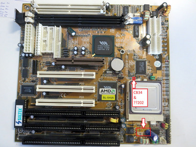
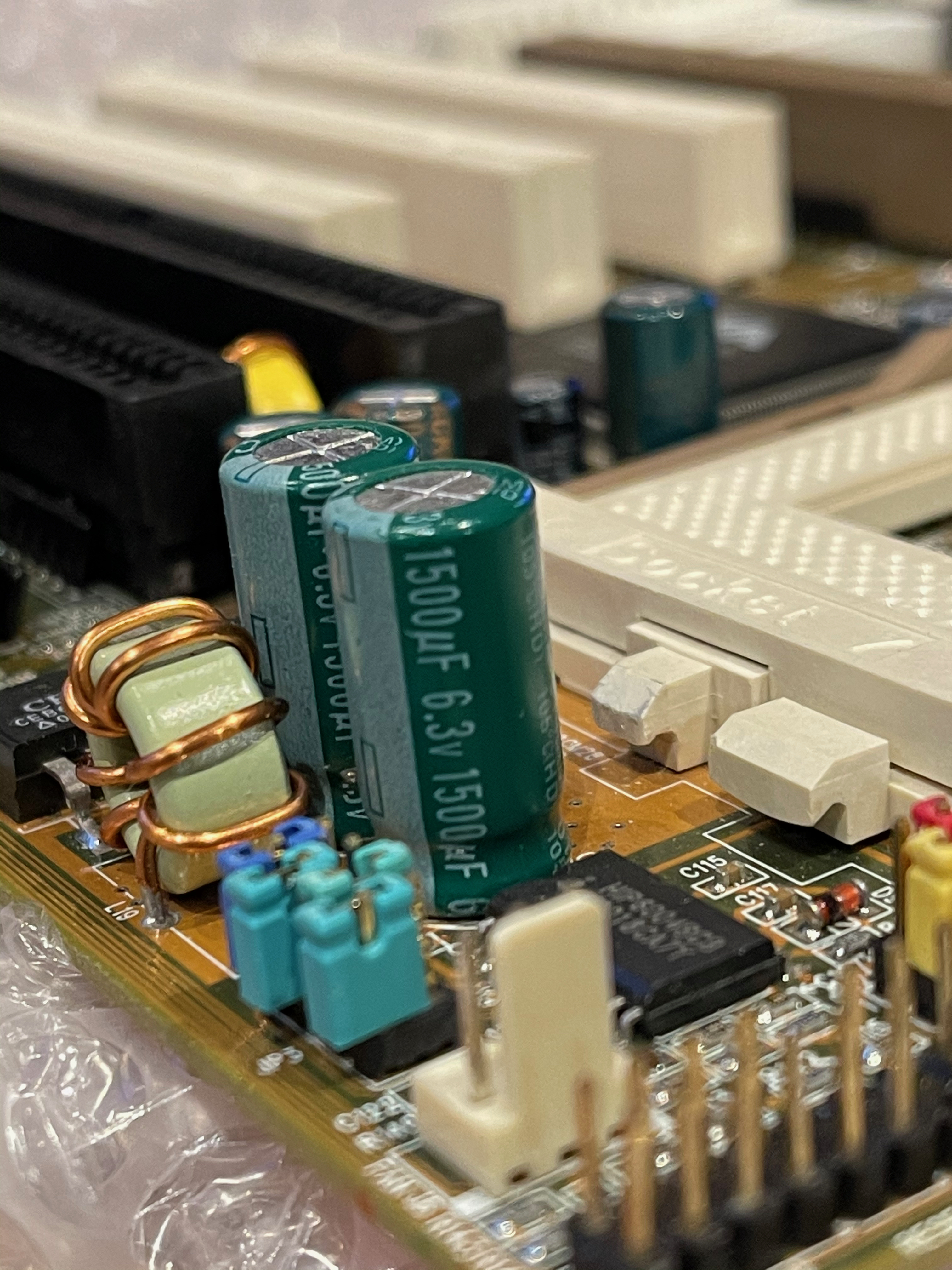
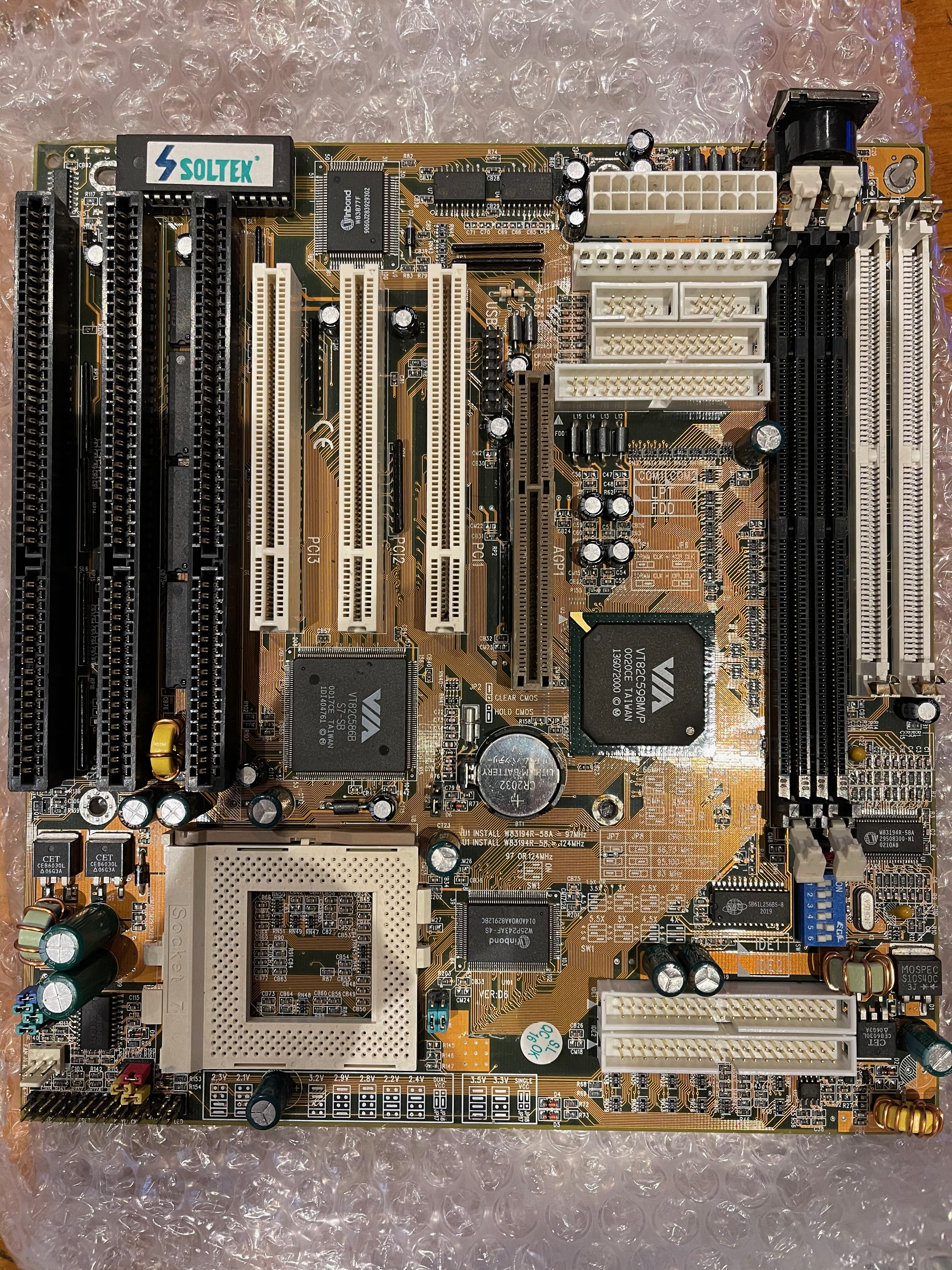
Hi, I’m attempting to repair this free “barn find” SS7 motherboard that suffers mainly from a, uh, previous repair attempt...(?) It’s missing a few components and I would very much appreciate it if someone would be able to help me to identify what exactly is missing. Or if someone happens to have the schematics for this board that would be superb! I think I have figured out everything else except the correct specs for the two big caps below the CPU socket and the two SMD components right above it.

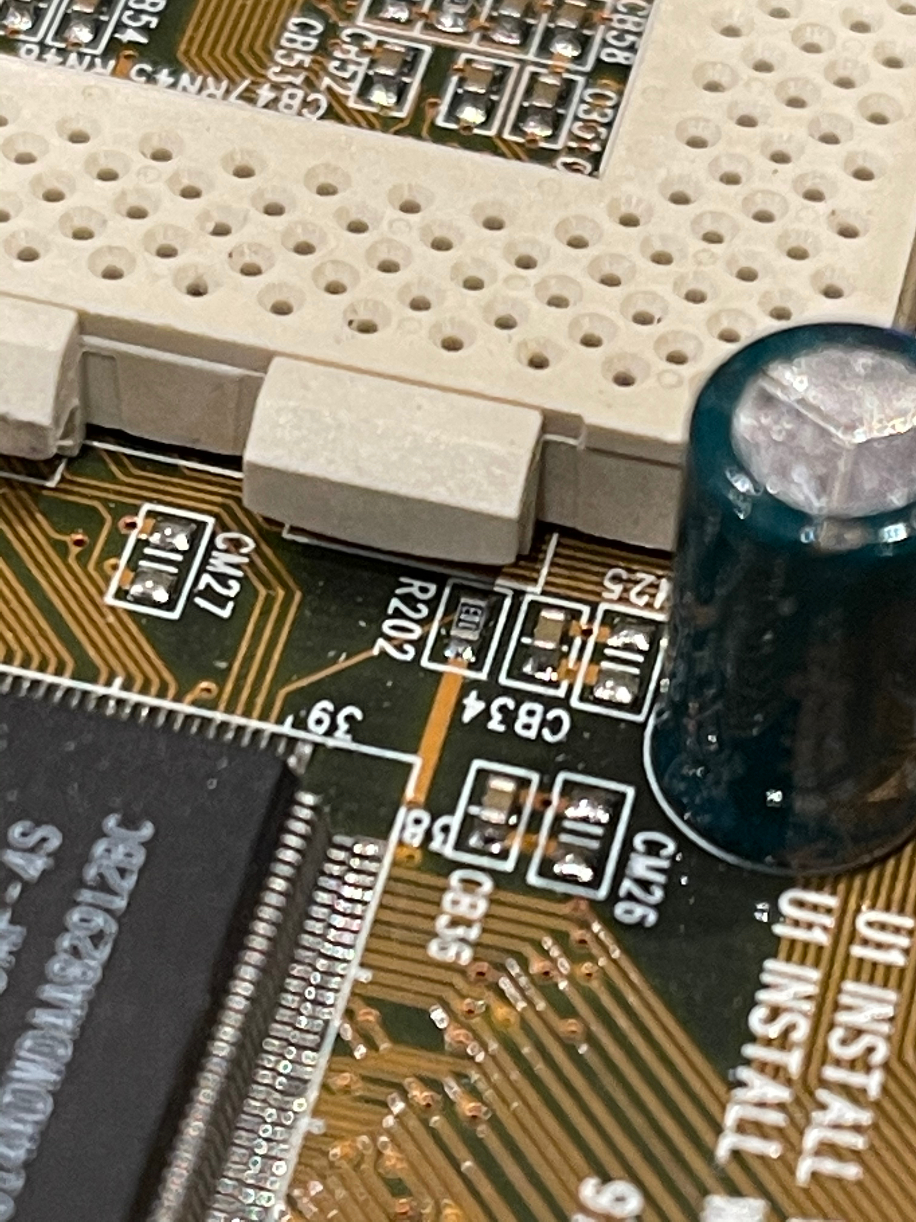
More precisely the missing SMDs are located at CB34 and the other one is right next to it and ends with *202 but the first digits have been literally knocked off the board.

1.jpg
Filename
1.jpg
File size
1.36 MiB
Views
963 views
File license
Public domain

That blue 10uf 250V cap partially hanging in there is not very helpful as a reference. I have no idea what’s the story behind that but perhaps the previous owner had some pretty epic overvolting in mind😅

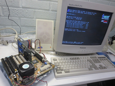
Anyway I've already cleaned up the board and thoroughly inspected it and couldn’t find any catastrophic physical damage. One trace was cut but that was an easy fix. I’d say there’s a good chance it might come back to life after replacing the missing components. Wouldn’t that be awesome!

I probably shouldn't but...

IMG_8400.JPG
Filename
IMG_8400.JPG
File size
381.51 KiB
Views
963 views
File license
Public domain

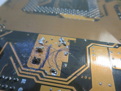
That looks just...painful. (It cleaned up surprisingly well tho)

Reply 1 of 26, by weedeewee

User metadata
Rank l33t
Rank
l33t

the two caps where the blue one is are easy to guess, anything 1000µF or over and 6v3 or over should do. unless my assumption of the voltage is wrong in which case, it's 12v or over.
that 202 looks like R202, and the CB34... those numbers sound so familiar, I'm pretty sure they've been posted somewhere, one some forum, sometime... 😁
also, it seems like there's a few more caps missing .

Right to repair is fundamental. You own it, you're allowed to fix it.
How To Ask Questions The Smart Way
Do not ask Why !
https://www.vogonswiki.com/index.php/Serial_port

Reply 2 of 26, by PcBytes

User metadata
Rank Oldbie
Rank
Oldbie

CB might be a ferrite SMD bead.

"Enter at your own peril, past the bolted door..."
Main PC: i5 3470, GB B75M-D3H, 16GB RAM, 2x1TB
98SE : P3 650, Soyo SY-6BA+IV, 384MB RAM, 80GB

Reply 3 of 26, by weedeewee

User metadata
Rank l33t
Rank
l33t
PcBytes wrote on 2021-04-21, 10:55:

CB might be a ferrite SMD bead.

doubtful, plenty of capacitors around the north & southbridge with the same CB# marking.

Right to repair is fundamental. You own it, you're allowed to fix it.
How To Ask Questions The Smart Way
Do not ask Why !
https://www.vogonswiki.com/index.php/Serial_port

Reply 4 of 26, by snufkin

User metadata
Rank Oldbie
Rank
Oldbie

From the other clusters of SM passives to the NW and SE of the Elite chip it looks like CBxx and CMxx would both be capacitors, but only the CB have been fitted (also along the AGP slot). Only CM I've seen fitted are down by the CPU regulator.

If no one comes up with a better source for values, might be worth measuring R201 (NW of Elite) and R203 (SE of Elite). If they're the same then there's a good chance R202 will match.

I like that they left you the legs of CT12.

Reply 5 of 26, by PuuFa

User metadata
Rank Newbie
Rank
Newbie

That was fast, thank you guys! That's a good idea about measuring R201 and R203 but unfortunately they're not the same. R201 is 10 kΩ and R203 is 470 Ω. I suppose I will probably need to find someone who has the same board for a reference? At least it seems quite certain now that CB34 should be a capacitor and R202 a resistor. Looking at google image search seems to confirm this. Now I just need to figure out the values.

And yes I know there's a few more caps missing but I figured that they're all just the usual 1000µF 6v3. About those 2 big ones I was thinking I could probably use 1500µF or 2200µF 6v3 but instead of just guessing I think it would be better to try find out what's actually supposed to be there.

Reply 6 of 26, by weedeewee

User metadata
Rank l33t
Rank
l33t

I've got a SL-54P5 board here, intel chipset, different layout, etc... couldn't tell from any photos I've got if there was a resistor/capacitor near the cpu socket. I'll have a look at the board later.

Right to repair is fundamental. You own it, you're allowed to fix it.
How To Ask Questions The Smart Way
Do not ask Why !
https://www.vogonswiki.com/index.php/Serial_port

Reply 7 of 26, by PuuFa

User metadata
Rank Newbie
Rank
Newbie
weedeewee wrote on 2021-04-21, 12:23:

I've got a SL-54P5 board here, intel chipset, different layout, etc... couldn't tell from any photos I've got if there was a resistor/capacitor near the cpu socket. I'll have a look at the board later.

Looking at the google images it looks very different but it might be worth to check anyway, thanks!

Reply 8 of 26, by snufkin

User metadata
Rank Oldbie
Rank
Oldbie

If you have trouble finding a good source of information then it might be worth making a few guesses.

That EliteMT chip looks like it could be something like this (I'm assuming SRAM chips have common pinouts):
https://www.digchip.com/datasheets/parts/data … 5L6464A-pdf.php

That looks like it'd make R201 a pull down for nCE2 & 3 (pin 126 & 125), R203 might go to ZZ (pin 63, strong pull down)? and R202 to MODE (pin 41)? If I'm not barking up completely the wrong tree then I don't see anything that specifies what the pull up or downs should be. It looks like the Mode pin might have an internal pull up, so if R202 does go to pin 41, and the other side of R202 goes to Gnd, then it would probably want to be a reasonably strong pull down (like the 470 ohm).

You can probably check if I'm way off by comparing where power pins are on the Elite chip and seeing if they match that data sheet.

Also, that chip has separate pins for the main power supply and the output buffers power supply, which might explain the CM and CB markings (could be separate power planes, coupled together by an inductor somewhere).

On the big caps, you can check to see if the +ve side goes to a power pin on the cpu. If it does then you should be safe with 6.3V, though I was always told for longevity to aim for rated voltage of 3x load, so 10V might be better. 250V is probably taking it a little far.

[edit to add:
Looks like UH19 could do with photos of the board as well:
http://www.win3x.org/uh19/motherboard/show/4626

There's a photo here (you've probably already seen it), but unfortunately not enough to get component values. But you can at least see which big caps are missing.
https://cdn.prohardver.hu/dl/uad/2017-07/3589 … 537866600_b.jpg

Also, probably a stupid question, but how sure are you that there were components fitted there? If there is an internal pull up on that pin, then there may not need to be an external resistor at all.
]

Reply 9 of 26, by PuuFa

User metadata
Rank Newbie
Rank
Newbie

That looks like it'd make R201 a pull down for nCE2 & 3 (pin 126 & 125), R203 might go to ZZ (pin 63, strong pull down)? and R202 to MODE (pin 41)? If I'm not barking up completely the wrong tree then I don't see anything that specifies what the pull up or downs should be. It looks like the Mode pin might have an internal pull up, so if R202 does go to pin 41, and the other side of R202 goes to Gnd, then it would probably want to be a reasonably strong pull down (like the 470 ohm).

Yes! It appears that you’re absolutely correct about the resistors. Thank you! I will go with the 470 ohm unless someone shows up with a reference board and says otherwise. In a hindsight I guess I should’ve figured that out by myself but to be fair this is the first time that I’m attempting this type of (missing components) repair without having full schematics for the board so it’s a bit of a learning curve.

On the big caps, you can check to see if the +ve side goes to a power pin on the cpu. If it does then you should be safe with 6.3V, though I was always told for longevity to aim for rated voltage of 3x load, so 10V might be better. 250V is probably taking it a little far.

Yeah the big caps go to the CPU power pins so I’m going with 6.3V. From what I’ve learned it should be optimal for this purpose. Well at least with good quality caps it should be. Again unless someone shows up with a reference board I’ll probably use either 1500uF or 2200uF Rubycon MCZ for these 2 and the rest I will do with 1000uF 6.3V Nichicon HM.

Now, that leaves only the CB34. I did some poking around and found that it has continuity to ground and CPU VCC pins so that should definitely help to figure out what it should be. However life tends to get in the way of hobbying so I’ll have to look at it again later in the evening or maybe tomorrow.

Looks like UH19 could do with photos of the board as well:
http://www.win3x.org/uh19/motherboard/show/4626

I wasn’t aware of UH19… I will take a look and if they really need photos of the board I’ll be glad to provide but, well, I better get this thing look presentable first.

Also, probably a stupid question, but how sure are you that there were components fitted there? If there is an internal pull up on that pin, then there may not need to be an external resistor at all.

No such things as stupid questions😉 I forgot to take close up shots and I’ve already prepped the pads so too late now but yes it was very obvious that a component was violently ripped off from these 2 spots.

Reply 10 of 26, by snufkin

User metadata
Rank Oldbie
Rank
Oldbie
PuuFa wrote on 2021-04-21, 16:49:

Now, that leaves only the CB34. I did some poking around and found that it has continuity to ground and CPU VCC pins so that should definitely help to figure out what it should be. However life tends to get in the way of hobbying so I’ll have to look at it again later in the evening or maybe tomorrow.

Most likely just a local decoupling cap for the cache, with no specific purpose or I'd expect it to be closer to whatever really needed it. 1uF probably a good shout? If you have access to a component tester then I'd just copy CB25. Bigger not necessarily better for decoupling caps as there needs to be a range of capacitance values to get a wide range of decoupling frequency (I'd have to look up the actual details of that). Wouldn't be surprised is the board worked without it, although running memtest for a day would help to prove that.

I wasn’t aware of UH19… I will take a look and if they really need photos of the board I’ll be glad to provide but, well, I better get this thing look presentable first.

I wasn't until recently either, but it looks like a good thing.

Reply 12 of 26, by PuuFa

User metadata
Rank Newbie
Rank
Newbie

My apologies for the delay. I've been a bit busy but I'm happy to report back with some pretty good results! Not yet 100% there but close.

2.jpg
Filename
2.jpg
File size
392.01 KiB
Views
808 views
File license
Public domain

Can't say how satisfying it was to see this when I plugged it in for the first time. It also passed all my stress tests and diagnostics without breaking a sweat but there were still a few issues to iron out.

After the initial success it just suddenly died on me. After disconnecting everything it came back to life just to be dead again the next morning. This I tracked down to a problem with the K6-2/450AHX CPU that came with the board. You can see in my first post that the voltage setting jumpers are set incorrectly. Of course I corrected them before plugging it in but who knows the previous owner might have been running it as it was... It didn't even match any documented settings but considering that the jumpers were kind of set for single VCC I suppose it's possible that the CPU got 3.3 volts or more. Ouch! No wonder it's not happy. I threw in some random K6-2/500 and the problem was gone. One fixed, few more to go.

Next annoying but not so critical issue was that Win98se would always freeze during shutdown. Not any drivers or updates would fix it but disabling ACPI in the BIOS did the trick. I installed Windows ME just to see how it would behave and discovered that ACPI works fine with it. I suppose this confirms that it's not a fault with the motherboard but just Windows 98 being it's quirky self, right? I faintly remember seeing this same behavior back in the day too with one or more systems... It's been a while.

Now, as far as I can tell there's only one issue left. The COM ports don't work. Both of them. That's quite inconvenient because I don't have a PS/2 bracket so no choice but to use a USB mouse. It only works in Windows tho so that's not exactly the ideal solution. Windows recognizes the COM ports but doesn't recognize anything connected to them so I assume there must be a broken trace or a cracked solder joint somewhere. This will need some more poking around but I'd appreciate any advice if there's something more that I should consider. I should add that there seems to be some level of connection happening when I hook up an old external serial port modem as an improvised test device. It briefly blinks some leds when I search for modems in Win98 but it just won't be recognized. Windows ME on the other hand gives a significantly more prominent reaction. Whenever I power on the modem ME will completely freeze and only unfreeze when I switch the modem off. If I boot ME with the modem connected and powered on it will freeze during the boot. So likely it's just one trace somewhere, right? Could I somehow identify which pin in the COM header is not doing it's job? That would narrow down my search quite a bit.

Reply 13 of 26, by mwdmeyer

User metadata
Rank Oldbie
Rank
Oldbie

I also have a Soltek SL-54U5 and my com ports don't worth either. I need to check with the ebay seller as I'm pretty sure they should.

It might be the rarer type with the different pin out? If you fix yours I would be interested!

Vogons Wiki - http://vogonswiki.com

Reply 14 of 26, by PuuFa

User metadata
Rank Newbie
Rank
Newbie
mwdmeyer wrote on 2021-04-25, 21:24:

I also have a Soltek SL-54U5 and my com ports don't worth either. I need to check with the ebay seller as I'm pretty sure they should.

It might be the rarer type with the different pin out? If you fix yours I would be interested!

Hmm that's interesting... I did check the pinout in the manual that I found online and it was the standard type but maybe there could be different board revisions with different pinouts. I'd imagine it's not very likely but why else would there be several boards having the same issue. Who knows. I do hope I can figure it out tho because I already used way too much time with this thing and would be a shame if it all goes to a waste.

By the way since you have the same board could you kindly check what exactly are those components that were missing from my board? I've already replaced them based on the suggestions here and my own consideration but it would be interesting to see how close to the original specs we got it.

Reply 16 of 26, by snufkin

User metadata
Rank Oldbie
Rank
Oldbie

Good to see it up and running. Don't know about the serial ports thought, so don't think I can help there. Worth checking if the motherboard is getting -12V from the PSU? Given what you've said about the header, I assume you've checked that the pins match up with the DB9? Doesn't look like it'd be too difficult to knock up a ps2 connector if necessary.

If you can, don't forget some decent photos of the whole board whilst it's out on the bench, for UH19.

Reply 17 of 26, by mwdmeyer

User metadata
Rank Oldbie
Rank
Oldbie

Let me know if you need more photos.

The CPU caps were replaced by the previous owner but I assume they are correct.

https://www.vogonswiki.com/images/7/78/Soltek … -54U5_CB34.jpeg
https://www.vogonswiki.com/images/7/7c/Soltek … 5_CPU_caps.jpeg
https://www.vogonswiki.com/images/b/b7/Soltek … otherboard.jpeg

Vogons Wiki - http://vogonswiki.com

Reply 18 of 26, by snufkin

User metadata
Rank Oldbie
Rank
Oldbie

Looks like R202 says 103 on it? In which case I'm wrong about that and it should be a 10k resistor. Probably doesn't matter as the large trace looks like it goes to pin 38, Vcc, and the MODE pin has an internal pull up. So MODE is just being pulled high internally and externally. Might even work without that resistor and just rely on the internal pull up.