CelGen wrote on 2021-05-01, 03:33:
With a freshly formatted floppy I can step between tracks and the read command seems to work but writing still fails. If the head selected is indicated by H0 or H1 then it is properly changing heads, otherwise it isn't.
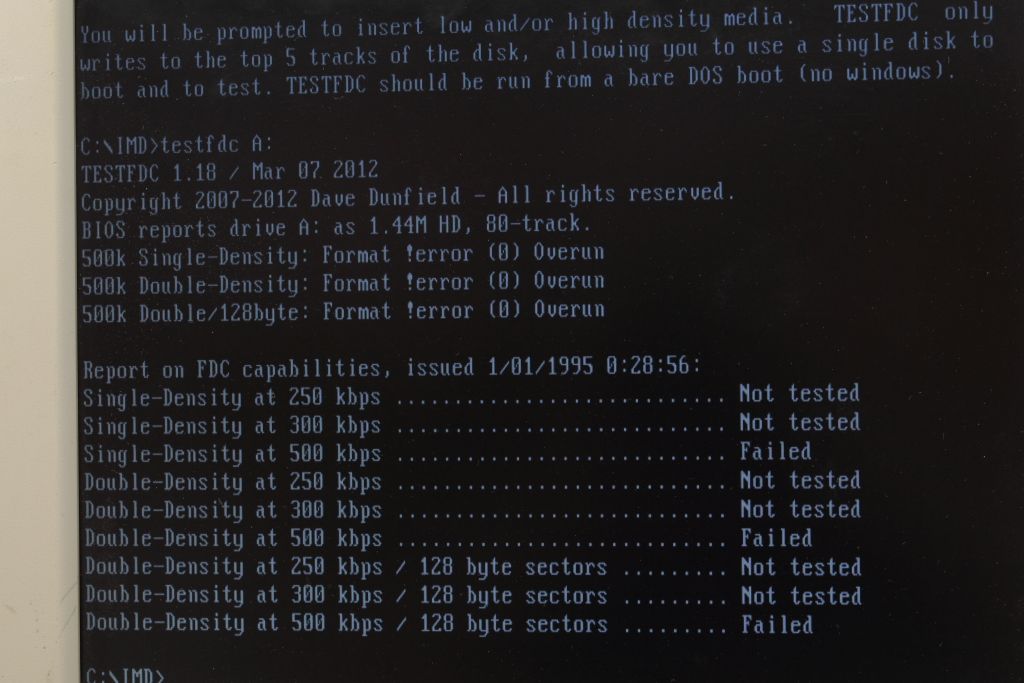
Ok, so I think that proves the FDC is reading data correctly from the disk. As I understand it, IMD is just checking a status register in the FDC to see if it throws a CRC error, so the data isn't actually moved to the motherboard. If the track 0 indicator is changing from 'Z' to 'z' then that suggests the FDC status registers can be read correctly. So it would probably be able to see if there had been a CRC error.
Power supplies sound fine. I think everything so far says this has to be a problem on the motherboard (you've tested controllers and drives elsewhere), and yet other cards can transmit data fine.
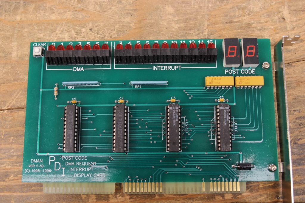
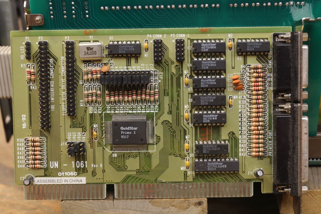
I'm sure this has already been covered, but on the controller card, does it have IDE ports with anything plugged in to them, and do they work correctly (this should test whether anything can get data across the bus from that particular card)? Can you post a photo of the card? I'm just wondering if there could be some issue with the FDC not being able to switch the bus lines fast enough (maybe some line capacitance issue?), but it should be buffered anyway. And you've tried multiple cards.
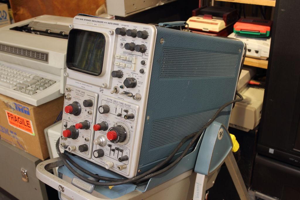
What sort of scope do you have? It'd be a fair bit of work, but I'm wondering if it's worth looking at a bus data line (not sure what to trigger off, maybe the index pulse on the floppy connector?), and comparing it with a different motherboard. Essentially just hunting around for when signals start looking different between a working system and this one.
Other than that though, I'm stumped.
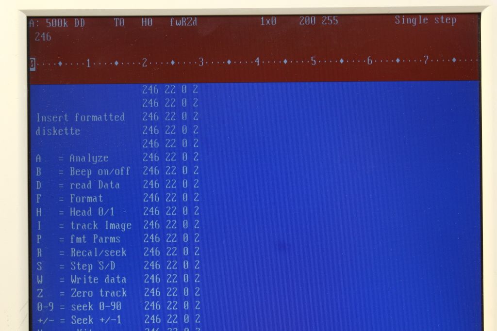
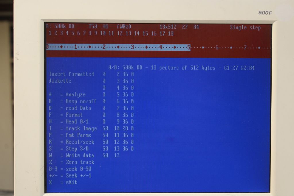
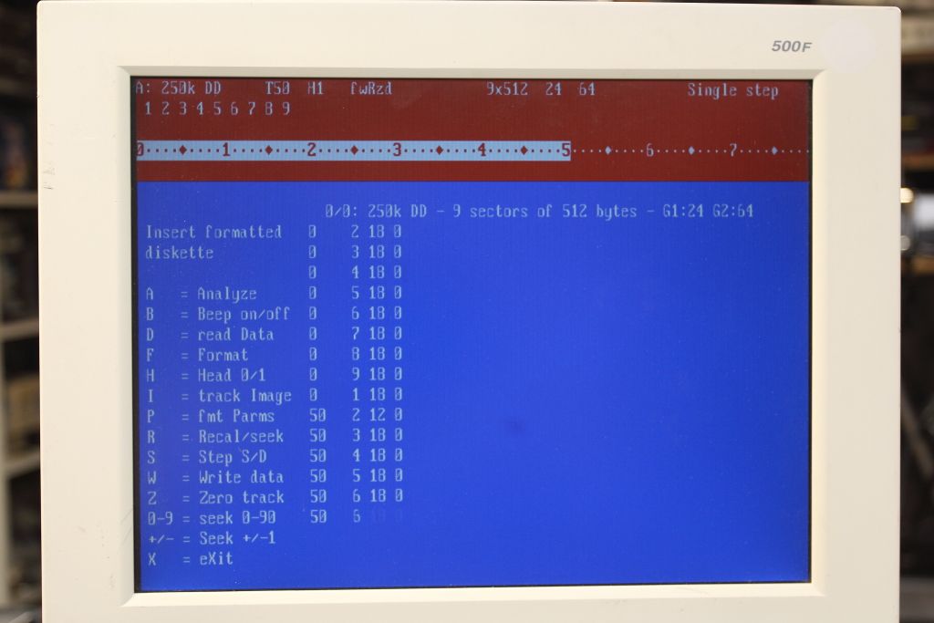
Oh, not sure if this would tell us anything, but try formatting a DD 720k floppy and see if any of the numbers in IMD alignment test change, particularly the sector number (which I think was stuck at 22 before).
Curiously while doing these tests I ran into quirks. On one occasion I got NO INTERRUPT FROM FDC that would not clear until I warm reset the machine. On another occasion the drive stopped responding entirely but IMD never reported any errors.
I had something similar happen (drive stopped responding) when I was doing bad things to a drive and trying to measure the timing pulse to the motor controller. But that was with a faulty drive I'd tried in multiple machines, whereas you've tested the drive and it's ok.
Still, maybe there are bus lines being driven directly by the FDC and it (plus all the FDCs on the other controllers) are struggling to drive the line. Or the other way round. If a line from the motherboard is slow to rise then it could throw signal timing out? With my broken drive I could compare the shape of RDATA with a good drive and it looked ok. I eventually found some completely missing pulses on the RDATA line from my broken drive, which has pointed me toward the analogue read stage since the digital stage looked ok.
Likewise I've been pulling my hair out on this board for nearly two weeks now. I'm getting very tempted to just swap in that test board and be done with it because I need my bench back soon. :U
Understood. I've spent far too long trying to get my broken floppy drive working. But it's so nearly working, so I can't just let it go, but have put it to one side for the moment. I find it much easier if something is clearly and definitely not working. At least then it's usually easier to identify the problem and decide if it's worth trying to fix. Situations where I feel there's probably just one duff capacitor, or a corroded but not broken track, and I can't find it, are annoying.

 "It's science. I ain't gotta explain sh*t"