Reply 20 of 26, by Ydee

Rank
Oldbie
- Rank
- Oldbie
Excellent job, sir - thank You very much, I'll do it tomorrow!
Excellent job, sir - thank You very much, I'll do it tomorrow!
So, done. But everything looks so much worse, than we expected.
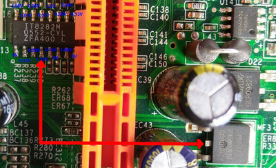
If I look at IT8282M pinout, we have many wrong values, as You can see on the pictures above - not only on pin 4 or 12. Instead expected VLDT 1,2V or VDDA 2,5V we have 0,03V and 0,28V and so on. I am affraid, it's a much more serious defect, than I can found and fix. I found pinout for IT8281M, but this is pin compatible with IT8282M, so we can use it.
Zero resistance I had measured between pin 4 and drain on one of NIKO SEMI, as is marked on picture. Unfortunatelly, I can´t found nothing, where is connected pin 12. Looks like it'll be safer to look for another mobo - I don't want to waste Your time. Anyway, thank you very much for your willingness and help, I appreciate it!

Ydee wrote on 2021-05-19, 14:15:So, done. But everything looks so much worse, than we expected.
If I look at IT8282M pinout, we have many wrong values, as You can see on the pictures above - not only on pin 4 or 12. Instead expected VLDT 1,2V or VDDA 2,5V we have 0,03V and 0,28V and so on. I am affraid, it's a much more serious defect, than I can found and fix. I found pinout for IT8281M, but this is pin compatible with IT8282M, so we can use it.
Zero resistance I had measured between pin 4 and drain on one of NIKO SEMI, as is marked on picture. Unfortunatelly, I can´t found nothing, where is connected pin 12. Looks like it'll be safer to look for another mobo - I don't want to waste Your time. Anyway, thank you very much for your willingness and help, I appreciate it!
(skip to the last paragraph if you like taking risks...)
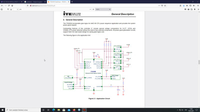
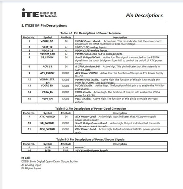
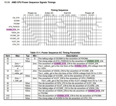
I don't think it's as bad as it looks really... I think what's supposed to happen is that U13 (power sequencer) keeps all the board supplies off to start with, so all the Sense lines will be wrong. Once the PSU is up, then it first turns on the Vdimm supply (pin 12 goes to 5V). When it sees the correct voltage on Vdimm_sen (pin 4) it turns on Vdda (pin 3 goes to 5V), then Vdd (woohoo, CPU on!), then Vldt (all that's according to that other datsheet I found a few messages back). At the moment it's stuck waiting for Vdimm_sen to be correct.
So, yes, a lot of voltages are wrong now, but I think if we can fix Vdimm, then U13 will then turn all the others on.
Using everything you've found so far... You've found that the Vdimm_sen comes from MF3 Drain. MF3 looks to be acting as a switch to connect whatever is on its Source to it's Drain when 12V is on the Gate. It's Source looks to be connected to the Source of MF4. MF4 looks like it's a switching regulator, fed by 3.3V at the Drain. So MF4 should be the Vdimm supply, but is only outputting 1.1V on pin 3.
It looks like that Vdimm supply also feeds a small regulator (U21) by the dimm slots, which should provide 1.25V. So that's another supply that'll be working if we can get 2.5V out of MF4.
I don't like giving up on a board, particularly when it feels like there's probably just one thing that's broken (in this case the RAM voltage). I've got suspicions about some components up near the CPU_12V connector, particularly that AS324 op amp. Notice that pins 8,9&10 are 3.4V, .45V and 1.04V. 3.4V looks a lot like the Gate input of MF4 and 1.05V the Source output. So I think that chip has might have something to do with controlling the output of MF4. There's also that GS431N up there that looks to be providing a 2.5V reference voltage. Maybe the opamp is supposed to match the MF4 output to that 2.5 reference, but there's a solder joint that's failed in that area.
On the other hand... tracking down the actual problem is likely to take a few more goes of trying to trace connections (at some point checking voltages isn't enough, we need to know what's actually connected to what), and that takes time, so I can understand that it might make more sense to look for another board. I went through this with a SlotA board and trying to trace all the power connections was maddening when I couldn't find where a connection went, and you can't overlook anything, even things like that MN6 by the 12V_CPU connector (that might be a switch to allow signals to the opamp or not).
.
.
.
Just had a slightly ugly thought to test whether it's worth trying to track down the actual fault...
Given the board already doesn't work, there's an ugly way to test the rest of the board, that comes with a (small, I think) risk of breaking things properly. Get a 2.5V power supply, or an adjustable power supply that can output 2.5V (there are some iffy looking ones on ebay for under £3). Unsolder and lift pin 3 of MF4. Solder a lead from that pad (leave the pin unconnected) and connect it to your external 2.5V supply. Turn on the motherboard, then turn on the 2.5V supply, and see if the rest of the board supplies start up. Probably wouldn't want to run with any components doing that, but would at least test the board.
[actually, a couple of AA rechargeables in series might be close enough to 2.5V... -ve to ground, +ve to the pad of MF4 pin 3]
I don't want to throw the motherboard away, I'm sure I'll try to do something with her, but at this moment I lack the necessary knowledge and equipment. Your knowledge and abilities are waaaaay ahead of mine!
That's why I want to postpone it for now and not waste Your time and willingness, because we don't know the history of the board, and we don't know whether it was functional at all, or whether it was removed from a no longer functioning PC.
I also thought about bypassing and bringing the right voltage to the necessary location - yes, I can try the MF4 idea and see what happens.
Thank you very much again for everything and I will report on any progress. Have a good days!
Ydee wrote on 2021-05-20, 14:05:I don't want to throw the motherboard away, I'm sure I'll try to do something with her, but at this moment I lack the necessary knowledge and equipment. Your knowledge and abilities are waaaaay ahead of mine!
Don't be too sure about those things, you made some tricky measurements (I struggle to see those pins around around the 8800 and 9605 without a magnifier) and can find and read datasheets, and it's not like I've actually found the cause of the problem.
yes, I can try the MF4 idea and see what happens.
Thank you very much again for everything and I will report on any progress. Have a good days!
If you do try it, measure the voltages on the enable and sense pins of the power sequencer to see if anything changes. And don't have a CPU or any RAM plugged in, as we don't really know what will happen.
Hope your next build has better luck and you actually get to use it, not just prod at it with a meter.
Ydee wrote on 2023-08-09, 10:15:Thank you very much, here´s why I asked: ECS 761GX-M754 no POST
I dont want hijack this thread.
Found somewhere on the internet.
page 30,31,32
Aopen MX3S, PIII-S Tualatin 1133, Radeon 9800Pro@XT BIOS, Diamond monster sound MX300
JetWay K8T8AS, Athlon DH-E6 3000+, Radeon HD2600Pro AGP, Audigy 2 Value
Thank you!
