VOGONS


MFM 5.25 floppy with 5ali61

Topic actions

Reply 20 of 49, by Deunan
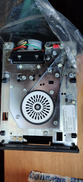
User metadata
Rank Oldbie
Rank
Oldbie
Joakim wrote on 2021-05-24, 11:52:

I am a little confused about the section about the power on page 11/19. I have a 4 pin Molex connector on my model, but I also have the 10 pin molex connectors. Is 4 pin molex is enough? Maybe the other connectors are there for compatibility reasons?

It looks like your drive needs DC only and it's the usual +5V and +12V - see section 7.0 in the PDF. That's good. On old model like this it's quite likely there are 2 separate power connectors for different systems. It seems you might have 3 of those, the PC-type Molex and two 90deg pin connectors. Not sure why J2 is there but J5 should have the same pinout as in the PDF. You can easily test the standard Molex then, middle pins should be GND, one side +5V (plug in a cable to make sure it's on the red wire side), the other side +12V. To make double sure you can trace the +5V to the logic chips, most TTL series have power input in the last pin (14/16).

If the power plug seems OK then connect just the power and see what it does. Preferably you should be doing it via a current-limited PSU because if there are any faulty tantalum caps there will be fireworks. Not too worry if that happens, can be usually easily repaired by cleaning the soot and replacing the offending part. With current-limited PSU you can see the excessive power draw and act before there is actual fire though.

Assuming no fireworks, put in a floppy and close the drive door. If there are issues with inserting a floppy investigate rather than use force, only drives that eject disks need a gentle push at the very end of floppy travel, everything else should be butter smooth. There should be no need to keep pushing the floppy to close the door in any kind of drive.
Most drives, though not all, will briefly start the spindle motor upon detecting floppy insertion or door closing - this is to help seat the floppy centered. Motor should stop after at most 10s or so. And heads should not be banging the end of travel limiters. If you get this automatic action it's a very good sign, means the electronics part is not completly dead.

Reply 21 of 49, by snufkin

User metadata
Rank Oldbie
Rank
Oldbie
Joakim wrote on 2021-05-24, 11:52:

I post the PDF that I managed to make last night but for some reason the pages are in the wrong order. Also some are missing but it is because they were simply were not in the package. Maybe they were full of (very bad) pictures and when they were printed 40 years ago someone probably wanted to save ink! 😀

Ah, shame, some of the online manuals for other manuals were very thorough, and there are a fair few variable resistors on this drive that it'd be nice to know what they do.

I have tried to compare the manual to the one online and it does not look to be exactly the same but I really have not put too much effort into it. On sheet 18/19 it sais "All waveforms shown high true." and I guess it means they are "pulled up true"?

I think they just mean that the waveforms as drawn are inverted from what the actual voltages are doing. Sheet 14/19 (page 1) says "All interface lines are low true.", which follows the normal floppy standard.

I am a little confused about the section about the power on page 11/19. I have a 4 pin Molex connector on my model, but I also have the 10 pin molex connectors. Is 4 pin molex is enough? Maybe the other connectors are there for compatibility reasons?

My interpretation of that is that some drive models only have the 10 pin connector J5 fitted, and drive models V and VI (I think that's this one) have a 4 pin connector fitted as well, that they can use instead. If you've got a multimeter you can check the connection between the 4 pin connector and J5 (pin 1->J5 pin 4, pin 2->J5 pin 3, pin 3->J5 pin 6, pin 4->J5 pin 7).

And I've just learnt that what everyone calls a molex is actually an Amp mate-n-lok:
https://en.wikipedia.org/wiki/Molex_connector … _Connectors.jpg

One thing I definitely don't understand are the diagrams on sheet 15/19 (page 8 in your scan). Don't know why there's both a 220 ohm pull up and a 330 ohm pull down. This may be some detail of the 74LS that I'm missing. Also, there mention of termination resistors on sheet 7/19, which I'm not sure where they are...

Deunan wrote on 2021-05-24, 10:30:

Your drive has/needs Head Load signal. No PC controller that I know of has an output to control that signal, but you can tie it with Motor On. Do note, depending on how the head mechanism works, if your PC hangs with the drive spinning (thus head still loaded) you might need to cut power first to safely remove the floppy. Note, Head Load must not be connected to Density Select which is present on pin 2 of PC FDCs, so re-route that wire or change it on the drive (with jumpers if there are any, or you could cut traces but preferably do that on the cable side).

Is there a particular problem that'll be caused by having Density Select connected to Head Load? I know they're obviously nothing to do with each other, but the manual seems to suggest that the drive will handle head loading fine either way. My understanding from the manual is that the for drives with a head load solenoid, the drive will lower the heads when the door is closed and either the drive is selected or Head Load is true (pulled low).

So if Density Select is connected to Head Load then either DenSel is high, in which case the drive will do Head Load when the drive is selected, with disk in and door closed. Or if DenSel is low then the drive will do Head Load with disk in and door closed (unaffected by drive select). I can see there'd be a possible problem if DenSel was a fast switching signal that might cause rapid load/unload events, but I don't think that's the case here? I'm pretty sure that PCs disable the motor when the drive isn't being accessed, which meets the manual recommendation of not leaving the disk spinning with heads loaded.

I think the only reason a separate Head Load input is there, is to save the 75ms it takes to for the heads to automatically load when changing between multiple floppy drives.

The manual also says Head Load only applies to "active drives (power on and door closed)". Which I read as meaning the heads will be unloaded if the door is opened. Door Open also cuts spindle power, so that should make it safe to remove the disk.

Ready, present on pin 4 on your drive,

pin 6 I think?

Reply 22 of 49, by Deunan

User metadata
Rank Oldbie
Rank
Oldbie
snufkin wrote on 2021-05-24, 13:22:

One thing I definitely don't understand are the diagrams on sheet 15/19 (page 8 in your scan). Don't know why there's both a 220 ohm pull up and a 330 ohm pull down. This may be some detail of the 74LS that I'm missing. Also, there mention of termination resistors on sheet 7/19, which I'm not sure where they are...

Line terminator. Old solution, designed for 74xx drivers. That's xx not LSxx because lower power series don't have enough current drive for resistors this small, and sure enugh these diagrams have non-LS drivers. Passive SCSI terminator is similar.

snufkin wrote on 2021-05-24, 13:22:

Is there a particular problem that'll be caused by having Density Select connected to Head Load? I know they're obviously nothing to do with each other, but the manual seems to suggest that the drive will handle head loading fine either way. My understanding from the manual is that the for drives with a head load solenoid, the drive will lower the heads when the door is closed and either the drive is selected or Head Load is true (pulled low).

We don't know if that manual is 100% correct for that particular drive model. Typically there are jumpers to select when head is (un)loaded and this might be semi-automatic like the manual says, or not. 75ms delay after selection is too long for faster systems and writes will fail, might also affect reads if the code doesn't retry properly or forces head seek every time read error happens. On PCs it's better to connect Head Load to Motor On because the latter has longer wait time, so heads will be fully loaded and stable by then.

In general the idea of loading heads only really applies to drives with permanently running AC motors, to reduce head wear (and somewhat also floppy wear), so a connection to Motor On signal makes even more sense. It's not unsafe to leave it connected to Density Select, simply might just not work that way.

snufkin wrote on 2021-05-24, 13:22:

The manual also says Head Load only applies to "active drives (power on and door closed)". Which I read as meaning the heads will be unloaded if the door is opened. Door Open also cuts spindle power, so that should make it safe to remove the disk.

Again this is just me not making assumptions. It'd be darn difficult to make a head load mechanism not release when the disc is unclamped but who knows. Also, the drive might be somehow faulty (say an electromagnet slug being stuck, the door switch not opening, etc). I've repaired a few drives, both 5.25" and 3.5" - I'm by no means an expert on the subject but I figure better safe then sorry. If the floppy doesn't want to slide out easily it should not be pulled, might just be blocked by the heads somehow. And if you rip those out, it becomes a nice looking box of spare parts.

snufkin wrote on 2021-05-24, 13:22:

Ready, present on pin 4 on your drive,

pin 6 I think?

Ah yes, my bad.

EDIT: Oh and BTW that drive might not even have a head load solenoid. Again the manual doesn't cleary state that, but does mention models with and without, and all will have that signal. Just like the actual motor type it's best to check.

Reply 23 of 49, by snufkin

User metadata
Rank Oldbie
Rank
Oldbie
Deunan wrote on 2021-05-24, 15:08:
snufkin wrote on 2021-05-24, 13:22:

One thing I definitely don't understand are the diagrams on sheet 15/19 (page 8 in your scan). Don't know why there's both a 220 ohm pull up and a 330 ohm pull down. This may be some detail of the 74LS that I'm missing. Also, there mention of termination resistors on sheet 7/19, which I'm not sure where they are...

Line terminator. Old solution, designed for 74xx drivers. That's xx not LSxx because lower power series don't have enough current drive for resistors this small, and sure enugh these diagrams have non-LS drivers. Passive SCSI terminator is similar.

Ah, so are both the 220Ω and 330Ω part of the termination, and only found on the last drive in a chain? I was thinking there would only be one termination resistor on each line. Do they pull the line to around 3V (so a logic one) with no current having to flow from the 7438 driver, and the driver just has to sink ~23mA through the 220Ω when it outputs low? Plus a bit for the internal pull up in the 74LS receiver that you told me about the other day? Is it just a coincidence that the 220Ω || 330Ω is not far off the 105Ω line impedance to minimize reflections?

We don't know if that manual is 100% correct for that particular drive model. Typically there are jumpers to select when head is (un)loaded and this might be semi-automatic like the manual says, or not. 75ms delay after selection is too long for faster systems and writes will fail, might also affect reads if the code doesn't retry properly or forces head seek every time read error happens. On PCs it's better to connect Head Load to Motor On because the latter has longer wait time, so heads will be fully loaded and stable by then.

True, the manual could be misleading and drive switches not working. And the (probable) long delay for the spindle to spin up would hide any possible Head Load delay (I did spot earlier that this may all be irrelevant if there is no Head Load solenoid). I'm slightly surprised that Head Load (either automatic or via Head Load+delay) isn't required for the drive to be ready. It also makes more logical sense to tie the Head Load to Motor Run, particularly in a PC, with independent Motor Run signals for A: and B:. I think I was approaching this from a 'minimum number of changes in order to see if the drive works' point of view, and DenSel -> Head Load didn't seem to actively break anything even if it didn't make any sense.

I've repaired a few drives, both 5.25" and 3.5" - I'm by no means an expert on the subject but I figure better safe then sorry. If the floppy doesn't want to slide out easily it should not be pulled, might just be blocked by the heads somehow. And if you rip those out, it becomes a nice looking box of spare parts.

More than me, I've only managed to fix a couple and most recently failed to fix a 3.5" drive that had all the jumpers to easily convert between PC and Shugart, which was a shame (I think a reference voltage input in to a custom chip used to sense the magnetic transitions was damaged when the zener diode that supplied said voltage failed, possibly due to the failed and leaky electrolytics).

And definitely agree on things moving smoothly, and watch out if they're not. I've got recollections of disks practically sliding right out of the drive just from the little spring catch. Certainly a lot more graceful than the 3.5" catapults.

Reply 24 of 49, by Joakim

User metadata
Rank Oldbie
Rank
Oldbie

Current limited PSU..? I don't own one. But I guess I could measure the current with a multimeter in series? Can also maybe test it outdoors and outside the computer case. 😀

I guess it ok to start the drive without having it connected to the motherboard?

If one would like to learn more about floppies, what sources do you recommend? I want to know more about the pin connections.

Reply 25 of 49, by snufkin

User metadata
Rank Oldbie
Rank
Oldbie
Joakim wrote on 2021-05-24, 17:38:

Current limited PSU..? I don't own one. But I guess I could measure the current with a multimeter in series? Can also maybe test it outdoors and outside the computer case. 😀

Not the whole PSU, just what each pin on a chip can handle. Probably a good idea to follow Deunan's advice on the post at the top of this page. Might want to try inserting and removing a floppy with no power first, just to see if that works mechanically.

I guess it ok to start the drive without having it connected to the motherboard?

Shouldn't break anything, and a good way to make sure nothing terrible happens with the capacitors and the like.

If one would like to learn more about floppies, what sources do you recommend? I want to know more about the pin connections.

I found this useful: https://www.hermannseib.com/documents/floppy.pdf

There are a few a links in this thread where I was trying (and not really succeeding) to help figure out why a drive could read DD but not HD, along with some cries of frustration that there doesn't seem to be a good source describing how floppies work: 2.88MB ED diskette drive troubles

Page 11 of this was quite funny: https://www.datasheetarchive.com/pdf/download … %2520MITSUBISHI

Reply 26 of 49, by Deunan

User metadata
Rank Oldbie
Rank
Oldbie
snufkin wrote on 2021-05-24, 17:07:

Ah, so are both the 220Ω and 330Ω part of the termination, and only found on the last drive in a chain?

That should be the case, yes. This is analog signal handling territory, I know a bit about that but again I'm no expert. In general you want to match the cable impendande but that's not fully possible in practical terms, there's always a cetain frequency range that you can cover and that's it. Then there is the question of actual impendance value, a lower one can improve signal quality but at the cost of having to both drive and dissipate more power. My understanding of this setup is this:
- the value of resistors is chosen to provide maximum damping of reflections and noise, but not so low as create excessive current draw or require special driving circuits (though SCSI, with more devices allowed on the bus and two such terminators on both ends, do use more powerful drivers)
- you want to have a stable logical level, but at the same time be close to Vcc/2 so that it's easier to swing the line both L and H with the same amount of current, thus timing would be close to identical - for TTL 3V is a good spot
- as a bonus having resistors tied both to GND and VCC gives you two power planes to dissipate power to, both should be low impendance (GND due to a lot of good connections, VCC due to having plenty of bypass caps around)
- reasonably small mismatch between terminator and line impedance is not such a big deal for low power transmission, the lower the power the less of an issue it is, and the extremes (short = 0hms, open = infinite impedance) are always worse then non-ideal termination for noise/reflections
- then there are secondary issues like cable capacitance and input capacitance, adhering to minimal rise/fall times considering TTL gates can pull to L way more than to H, meeting voltage margins for H/L levels, etc.

Many older drives use a simpler setup with 150 ohm pull-up resistors (since the driver outputs are open collector type gates). This is not as good and VCC plane has higher impedance than GND but on the other hand you get better defined H state with higher voltage. It's often a compromise of some sort with terminators, and it sure is nice to have them work as pull-ups rather than just dissipate power into heat all the time. Then the newer drives with better, less noise-prone electronics, use 1k pull-ups that can be permanently present on all devices on the cable since they don't source as much current. 1k-equipped drive might even work OK with 150ohm one on the same bus, thought it's not guaranteed.

snufkin wrote on 2021-05-24, 17:07:

I'm slightly surprised that Head Load (either automatic or via Head Load+delay) isn't required for the drive to be ready.

EDIT: Bah, Vogons mangled my post and lost half of it. Quick re-edit:
The older the drive, the more simple the logic. Newer ones can actually detect Index pulses and decide if the spindle motor is up to speed or not, the older ones just have a bunch of internal timers and that's it.

snufkin wrote on 2021-05-24, 17:07:

I've got recollections of disks practically sliding right out of the drive just from the little spring catch. Certainly a lot more graceful than the 3.5" catapults.

Never seen one myself but YT has some slot-loaded floppy drivers. Good luck pulling the floppy out without tools if it gets stuck (software hangs or the power is lost). Then there are multi-speed Apple drives that have software controlled eject function - and no mechanical button. Because Apple.

Reply 27 of 49, by Deunan

User metadata
Rank Oldbie
Rank
Oldbie
Joakim wrote on 2021-05-24, 17:38:

Current limited PSU..? I don't own one. But I guess I could measure the current with a multimeter in series? Can also maybe test it outdoors and outside the computer case. 😀

Well you can, at least you'll know how much power it actually needs, but the point was to limit the current in case of a short. Other than the fuse in the meter you won't have any of that. But you work with what you have

Joakim wrote on 2021-05-24, 17:38:

I guess it ok to start the drive without having it connected to the motherboard?

Not only OK, I'd start with that. Reason being, if it's somehow toast at least it will catch fire by itself and not take the mobo and other parts with it. First see if you can insert/remove a floppy on unpowered drive, then power and try again, see if the drive does anything weird like the heads trying to exit the case (or you know, smoke, fire, loud noises in general).

Reply 28 of 49, by evasive

User metadata
Rank Oldbie
Rank
Oldbie
snufkin wrote on 2021-05-23, 21:08:
Joakim wrote on 2021-05-23, 17:26:

So I picked up the drive and it looks to be in almost mint condition except for some bent pins.

Lovely. Really like those curvy, organic traces (I guess hand drawn) around the Micropolis logo.

It looks like the entire PCB has been hand-drawn using nothing more than a simple ruler. Those were the days indeed you can still design a PCB from scratch with pencil and paper...

Reply 29 of 49, by Joakim

User metadata
Rank Oldbie
Rank
Oldbie

So a an update. I got hold of some floppy disks! They are of questionable quality but works for testing the machanics of the drive.

Put in a disk and it moved flawlessly and without any effort. Into the drive (it was off). It also ejected without any problems. So I guess that's nice.

I have not bought a cable yet in Sweden. I guess I have to go abroad on eBay. Not very tempting to buy a 30 year old cable that I don't know if it works for like 20$ though..

Oh and I did not take a picture from below. The motors should be DC I think as you have that 60 and 50 Hz pattern on the wheel? I read that DC drives had that in one of the links you posted. It does not seem to be able to switch rpm mechanically though, as some drives had according to info in one link.

IMG_20210528_202217.jpg
Filename
IMG_20210528_202217.jpg
File size
1.52 MiB
Views
387 views
File license
Fair use/fair dealing exception

Reply 30 of 49, by snufkin

User metadata
Rank Oldbie
Rank
Oldbie
Joakim wrote on 2021-05-28, 18:18:

Oh and I did not take a picture from below. The motors should be DC I think as you have that 60 and 50 Hz pattern on the wheel? I read that DC drives had that in one of the links you posted. It does not seem to be able to switch rpm mechanically though, as some drives had according to info in one link.
IMG_20210528_202217.jpg

Not sure if that tells you about whether the motor is AC or DC, that's more to check the rpm of the spindle. Everything so far sounds like it's 12V DC. I think that if it's spinning at the right speed then the 50Hz patten should be static when viewed under a florescent light (or something that flickers at the mains voltage.

Have you tried connecting a power to it?

Reply 31 of 49, by Joakim

User metadata
Rank Oldbie
Rank
Oldbie

Nope not tried it yet. It is a little impractical but I'll get around to it! Might even film it then it's bound not to start smoking I guess. hehe...

From your linked floppy.pdf: "Old floppy drives use a DC-motor with a variable resistor to adjust the speed. They often have a
stroboscope ring on their bottom for that purpose. Modern drives hav e brushless motors."

Reply 32 of 49, by snufkin

User metadata
Rank Oldbie
Rank
Oldbie
Joakim wrote on 2021-05-28, 19:25:

Nope not tried it yet. It is a little impractical but I'll get around to it! Might even film it then it's bound not to start smoking I guess. hehe...

Is this a variant on 'a watched pot never boils'? A watched capacitor never explodes in flaming fragments?

From your linked floppy.pdf: "Old floppy drives use a DC-motor with a variable resistor to adjust the speed. They often have a
stroboscope ring on their bottom for that purpose. Modern drives hav e brushless motors."

From what Deunan said about AC motors in early drives, it's possible that the 'old' there might not be very old compared to some drives. But the manual sounds like this one is DC, so not a problem. It'll be interesting to see how well the strobe works. I'm not sure what modern lighting would be best to use; I imagine there are phone apps to strobe the camera light.

Reply 34 of 49, by snufkin

User metadata
Rank Oldbie
Rank
Oldbie
Joakim wrote on 2021-05-28, 21:15:

Hmm interesting idea. I happen to have an old lightbulb, but my wiring is 50 Hz, and this drive is 360 rpm I believe. (If it matters at all.)

I think incandescent light bulbs are too steady to have much of a strobe effect (the filament doesn't change temperature fast enough). I think some CFL have faster flicker rates than the mains. So it might only work with old fluorescent tubes. I think I was expecting this drive to spin at 300rpm, sheet 10/16 talks about the timing diagram showing a 16 sector 300rpm disk. Also wikipedia lists quad density 5.25" as 300rpm.

Still, find out when it spins.

Reply 35 of 49, by Deunan

User metadata
Rank Oldbie
Rank
Oldbie
Joakim wrote on 2021-05-28, 18:18:

Oh and I did not take a picture from below. The motors should be DC I think as you have that 60 and 50 Hz pattern on the wheel?

I was going to ask about the bottom photo, but forgot. Yeah, a pattern like that is unnecessary on AC motor, these are synced to the mains frequency, that's the whole idea. So this should be a DC one, which we already kinda figured by the lack of AC power input.

The belt might be an issue. Usually they either dry and break or turn into sticky mess that has to be properly cleaned from anything it was in contact with. Perhaps this one was replaced - inspect the wheels, make sure there's no black residue left. To be precise, you don't care about anything that looks like a proper coat of paint even if it's black. The residue I'm talking about is usually spots, often uneven (can be felt with fingertip) and sometimes still sticky. Your drive looks clean to me but it never hurts to make sure.

The belt is not supposed to be strechy (unlike rubber ones, which BTW can be used in a pinch to test the drive but not for long time operation), just enough to put it on the wheels and that's it. If it seems loose it will start slipping and might require replacing even looking OK otherwise. It's sometimes hard to get a proper replacement these days so pay attention not to damage yours. I don't think it needs saying but just in case, since I've seen the insane amount of various lubricants that people put on these drives on YT - no lubricant of any kind is to get anywhere near this belt, and that includes dirty fingers. Or you will need a new one.

Reply 36 of 49, by Joakim

User metadata
Rank Oldbie
Rank
Oldbie

Actually according to seller and documentation it was never used so I doubt it was changed. In that case probably sometime in the 1980s.. I will check for spots, but it's hard to know if it feels ok without experience. Guess I'll just run it and see how it fares.

I still have a really hard time finding one of those 5.25" connectors. Actually there is an other 5.25 drive on auction in my area, albeit broken. It comes with a cable so I might bid on it and end up with a much newer, broken drive too. 😀

Reply 37 of 49, by Joakim

User metadata
Rank Oldbie
Rank
Oldbie

So I just recently picked up a slot connector floppy cables. Its one of them old school long ones for a lot of drivers, two of them slot connected a twisted one on the end.

This topic does have a stupid name already but it might be renamed to how to blow up a socket 7 system with an ancient floppy drive from hell. I will use my least favorite PSU to test it first though..

Reply 38 of 49, by weedeewee

User metadata
Rank l33t
Rank
l33t

FYI, if the cable has 5 connectors, 3 34 pin IDC 2 34 pad slot connectors, with one pin connector on one end, and the other four on the other end, where two, one pin, one slot connector are seperated via a twist in the cable from the other two connectors.
The cable is only for two floppy drives.

Right to repair is fundamental. You own it, you're allowed to fix it.
How To Ask Questions The Smart Way
Do not ask Why !
https://www.vogonswiki.com/index.php/Serial_port

Reply 39 of 49, by BitWrangler

User metadata
Rank l33t++
Rank
l33t++
snufkin wrote on 2021-05-28, 21:32:
Joakim wrote on 2021-05-28, 21:15:

Hmm interesting idea. I happen to have an old lightbulb, but my wiring is 50 Hz, and this drive is 360 rpm I believe. (If it matters at all.)

I think incandescent light bulbs are too steady to have much of a strobe effect (the filament doesn't change temperature fast enough). I think some CFL have faster flicker rates than the mains. So it might only work with old fluorescent tubes. I think I was expecting this drive to spin at 300rpm, sheet 10/16 talks about the timing diagram showing a 16 sector 300rpm disk. Also wikipedia lists quad density 5.25" as 300rpm.

Still, find out when it spins.

Cheap LEDs have a bit of flicker, I think they use one string for the pos cycle and another string for the neg cycle though so are 120Hz (In North America, that would be 100 in Europe I guess.)

Unicorn herding operations are proceeding, but all the totes of hens teeth and barrels of rocking horse poop give them plenty of hiding spots.