VOGONS


Olivetti PCS33 (386 SX)/M-300 - Repairing

Topic actions

Reply 40 of 125, by Deunan

User metadata
Rank Oldbie
Rank
Oldbie

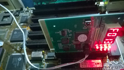
Oops, I went over the photos again and now I see the thing I thought was a reset button is in fact HDD activity LED - my bad. It seems this mobo doesn't even have a manual reset input.

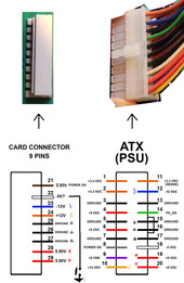
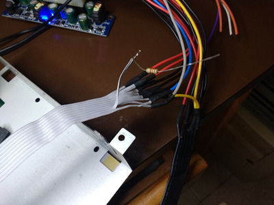
I'm still not 100% sure about the white and brown wires from the PSU. On one of the photos you've made of the PSU PCB there is a description and brown is called STB, while white is RES. Which I understand to be STANDBY and RESET. Other voltages are +/- 12V and +5V, there doesn't seem to be -5V mentioned.
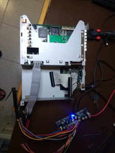
On most PCs the standby 5V only came with ATX power supplies but I know of a few (non-PC) old platforms that had soft on/off PSUs in very early '90 so it's not impossible. The button on your PSU probably goes to the front panel? This would mean it is a PSU capble of providing standby +5V.

So, ignore my pervious resistor suggestion. Instead try this:

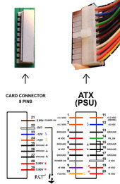
1) Get a SPDT switch, any kind would do, you could in fact do this with wire too but switch is easier to operate. Connect one side input to GND, the other side to +5V, and the middle output to 100 ohm resistor. Other side of the resistor connect to white wire pin on motherboard. This switch will now be your RESET/PWR_GOOD signal and you can flip it manually as well. Plus it provides both GND and +5V in case this mobo needs reset signal inverted vs what is the usual norm.

2) Connect brown wire pin on mobo to +5V via another 100 ohm resistor. This should provide some standby voltage and the resistor some protection as well in case the PSU markings are wrong. I would expect this powers things like RTC but not much else. Once you power up make sure this resistor is not getting hot, and preferably also measure the actual voltage at the mobo pin - knowing the voltage and 100 ohm resistance it's trivial to calculate the actual power draw of this line.

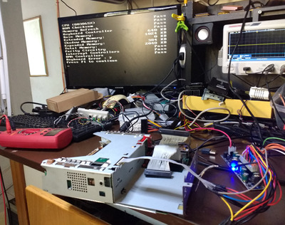
After powering up try flipping the switch a couple times, always give it a good few seconds to let the computer boot. Hopefully one position will work. If not then perhaps there is some motherboard damage, like the soldered memory going bad...

Reply 43 of 125, by PC@LIVE

User metadata
Rank Oldbie
Rank
Oldbie

I saw that you are working on an old Olivetti PC, I remember a similar PC (about twenty years ago), I extracted the HDD, the disk was working until a few years ago, unfortunately I think due to an incorrect setting of the jumper, what appears to be an SMD capacitor has blown, maybe if you wanna post a picture, in case can you tell me what exactly it was?
Returning to your PC, recently in my free time I am fixing various PCs, and the PCI-ISA POST CARD is useful, it displays the error codes, and this allows me to understand where the problem could be, I don't know if you use one, but if you use it it's not essential but it helps a lot.
I have seen the last contact cleaning work you have done, congratulations on the job, if you can explain the problem that the PC has, I will try to help you solve it.

AMD 286-16 287-10 4MB HD 45MB VGA 256KB
AMD 386DX-40 Intel 387 8MB HD 81MB VGA 256KB
Cyrix 486DLC-40 IIT387-40 8MB VGA 512KB
AMD 5X86-133 16MB VGA VLB CL5428 2MB and many others
AMD K62+ 550 SOYO 5EMA+ and many others
AST Pentium Pro 200 MHz L2 256KB

Reply 44 of 125, by dataino.it

User metadata
Rank Member
Rank
Member

My PCS-11 has started, the ATX power supply connection circuit (or pico PSU in may case ) is correct except for the brown wire which is the reset that comes from the original power supply, inserting the test board in fact without that wire connected the resetis off , insert a resistance in series (330 ohm) and a switch to ground the pc turns on by pressing the button, now Igo to insert a reset generator (nee555) to make the computer turn on when the power supply is turned on and a push button for the real reset.

Attachments

  • 21071507374425187817494671.jpg
    Filename
    21071507374425187817494671.jpg
    File size
    92.69 KiB
    Views
    1123 views
    File license
    Public domain
  • a.jpg
    Filename
    a.jpg
    File size
    553.68 KiB
    Views
    1239 views
    File license
    Public domain
  • b.jpg
    Filename
    b.jpg
    File size
    291.95 KiB
    Views
    1239 views
    File license
    Public domain
  • c.jpg
    Filename
    c.jpg
    File size
    432.15 KiB
    Views
    1239 views
    File license
    Public domain
Last edited by dataino.it on 2021-07-19, 20:22. Edited 1 time in total.

Reply 45 of 125, by BitWrangler

User metadata
Rank l33t++
Rank
l33t++

I am very curious about these Pico ATX supplies, it seems like my Dustin the DOStin build could use one ( Ratty build for self amusement, Dustin the DOStin.... ) but specs I see on eBay have them at about 8A on 5V and 8A on 3.3 which I think might be a bit low for an s370 build, but is probably fine for 386/486/Socket5.

Unicorn herding operations are proceeding, but all the totes of hens teeth and barrels of rocking horse poop give them plenty of hiding spots.

Reply 46 of 125, by dataino.it

User metadata
Rank Member
Rank
Member
BitWrangler wrote on 2021-07-18, 15:16:

I am very curious about these Pico ATX supplies, it seems like my Dustin the DOStin build could use one ( Ratty build for self amusement, Dustin the DOStin.... ) but specs I see on eBay have them at about 8A on 5V and 8A on 3.3 which I think might be a bit low for an s370 build, but is probably fine for 386/486/Socket5.

Yes, the power supply in question is designed to give maximum power on the 3.3V line.

Is fine for 286/386/486 and same Pentium, I don't have a powerful enough 12V power supply (I use 3.3A) but I could do a test with a UPS battery and see if it can turn on a pentium II.

Reply 47 of 125, by BitWrangler

User metadata
Rank l33t++
Rank
l33t++

There used to be a lot of cheap power bricks around for running 12V lighting that were 100-300 watts. Then there's some server supplies around that one could use externally as a power brick, that are 12V only with 500-1200W range, but the fans in those might howl a bit. If they are controlled though the higher wattage ones might be quiet at low output. Also a type to look out for in thrift stores are power adapters for powered coolers/iceboxes and AC adapters for vehicle accessories which may do 5-8A of 12V. I haven't seen one of these Olivettis close up (Well once or twice years ago) to eyeball if the small form factor (SFF) "TFX" style supplies, like I'm trying to cram into Dustin the DOStin might fit, but that would be a "straight to wall voltage" solution, but still needs adapting from ATX style to AT connector.

Unicorn herding operations are proceeding, but all the totes of hens teeth and barrels of rocking horse poop give them plenty of hiding spots.

Reply 48 of 125, by Verax

User metadata
Rank Newbie
Rank
Newbie
PC@LIVE wrote on 2021-07-17, 21:08:

I saw that you are working on an old Olivetti PC, I remember a similar PC (about twenty years ago), I extracted the HDD, the disk was working until a few years ago, unfortunately I think due to an incorrect setting of the jumper, what appears to be an SMD capacitor has blown, maybe if you wanna post a picture, in case can you tell me what exactly it was?
Returning to your PC, recently in my free time I am fixing various PCs, and the PCI-ISA POST CARD is useful, it displays the error codes, and this allows me to understand where the problem could be, I don't know if you use one, but if you use it it's not essential but it helps a lot.
I have seen the last contact cleaning work you have done, congratulations on the job, if you can explain the problem that the PC has, I will try to help you solve it.

YEs very old indeed. 😀 I don't really know sorry, i'm not a specialist sadly i am a really beginner in all of that. 😒

So you think i should get a POST CARD? Okay i'll take a look then, do you have a model to recommand?

Thanks! I'm trying to understand the whole thing and take everything one by one, and now things are getting close, it may be the Keyboard Controller that's failing. And so the post it stopping on that and can't go further. But i'm not 100% sure.

I invite you to read all of the message from the first page if you want a detail understanding of the situation and how it evolved. 😉

Reply 49 of 125, by Verax

User metadata
Rank Newbie
Rank
Newbie
dataino.it wrote on 2021-07-18, 14:56:

My PCS-11 has started, the ATX power supply connection circuit (or pico PSU in may case ) is correct except for the brown wire which is the reset that comes from the original power supply, inserting the test board in fact without that wire connected the resetis off , insert a resistance in series (330 ohm) and a switch to ground the pc turns on by pressing the button, now Igo to insert a reset generator (nee555) to make the computer turn on when the power supply is turned on and a push button for the real reset.

Wow thanks, that's a lot of informations, could you tell me where did you find those kind of stuffs? Like the resistance and the reset generator please? All of this is new to me i got to admit. 😀

I may try the same as you, and i'll tell you if it changes something!

Reply 50 of 125, by Deunan

User metadata
Rank Oldbie
Rank
Oldbie
dataino.it wrote on 2021-07-18, 14:56:

My PCS-11 has started, the ATX power supply connection circuit (or pico PSU in may case ) is correct except for the brown wire which is the reset that comes from the original power supply, inserting the test board in fact without that wire connected the resetis off , insert a resistance in series (330 ohm) and a switch to ground the pc turns on by pressing the button, now Igo to insert a reset generator (nee555) to make the computer turn on when the power supply is turned on and a push button for the real reset.

What powers the RTC clock when the system is off? I didn't see any battery or connector for it?
So prehaps the brown wire called STB is not standby voltage but standby function (in other words, a soft-on/off switch). Since your system works you could try to make the same resistor + switch circuit for the white RES wire as well. So that we can figure out if it is a RESET or PWR_GOOD signal of some sort.

Reply 51 of 125, by paradigital

User metadata
Rank Oldbie
Rank
Oldbie
Deunan wrote on 2021-07-19, 10:55:
dataino.it wrote on 2021-07-18, 14:56:

My PCS-11 has started, the ATX power supply connection circuit (or pico PSU in may case ) is correct except for the brown wire which is the reset that comes from the original power supply, inserting the test board in fact without that wire connected the resetis off , insert a resistance in series (330 ohm) and a switch to ground the pc turns on by pressing the button, now Igo to insert a reset generator (nee555) to make the computer turn on when the power supply is turned on and a push button for the real reset.

What powers the RTC clock when the system is off? I didn't see any battery or connector for it?
So prehaps the brown wire called STB is not standby voltage but standby function (in other words, a soft-on/off switch). Since your system works you could try to make the same resistor + switch circuit for the white RES wire as well. So that we can figure out if it is a RESET or PWR_GOOD signal of some sort.

On both the PCS 11 and PCS 33 there is a coin cell battery. On the PCS 11 this is on the front-panel board (which itself breaks out of the ISA riser board), on the PCS 33 this battery is on the ISA riser board itself.

Only the PCS 11 has soft power-on, and that momentary power switch and related circuitry is built into the PSU which butts up against the front panel. The PCS 33 has a mechanical linkage between the power button and the PSU, which operates the usual AT style latching switch.

Reply 52 of 125, by dataino.it

User metadata
Rank Member
Rank
Member
Verax wrote on 2021-07-18, 22:50:
dataino.it wrote on 2021-07-18, 14:56:

My PCS-11 has started, the ATX power supply connection circuit (or pico PSU in may case ) is correct except for the brown wire which is the reset that comes from the original power supply, inserting the test board in fact without that wire connected the resetis off , insert a resistance in series (330 ohm) and a switch to ground the pc turns on by pressing the button, now Igo to insert a reset generator (nee555) to make the computer turn on when the power supply is turned on and a push button for the real reset.

Wow thanks, that's a lot of informations, could you tell me where did you find those kind of stuffs? Like the resistance and the reset generator please? All of this is new to me i got to admit. 😀

I may try the same as you, and i'll tell you if it changes something!

I'm making a circuit after the test i post it.

Reply 53 of 125, by PTherapist

User metadata
Rank Oldbie
Rank
Oldbie
dataino.it wrote on 2021-07-18, 14:56:

My PCS-11 has started, the ATX power supply connection circuit (or pico PSU in may case ) is correct except for the brown wire which is the reset that comes from the original power supply, inserting the test board in fact without that wire connected the resetis off , insert a resistance in series (330 ohm) and a switch to ground the pc turns on by pressing the button, now Igo to insert a reset generator (nee555) to make the computer turn on when the power supply is turned on and a push button for the real reset.

This is very interesting info. The PSU on my PCS-11 has recently died, it sprung back to life at the weekend then refused to turn on again today. So I'll have to give this idea a go, it certainly sounds promising.

paradigital wrote on 2021-07-19, 11:11:

Only the PCS 11 has soft power-on, and that momentary power switch and related circuitry is built into the PSU which butts up against the front panel. The PCS 33 has a mechanical linkage between the power button and the PSU, which operates the usual AT style latching switch.

That's interesting, so that's what the power button is supposed to do!

On my PCS-11 ever since I got it given to me free/2nd hand in the early 2000s, the computer would switch on only from the switch at the back of the PSU and the soft power button on the front only seemed to trigger a relay which turned the LED orange and locked the keyboard until pressed again. It never controlled any power functions.

Reply 54 of 125, by PC@LIVE

User metadata
Rank Oldbie
Rank
Oldbie
Verax wrote on 2021-07-18, 22:39:
YEs very old indeed. :) I don't really know sorry, i'm not a specialist sadly i am a really beginner in all of that. :-/ […]
Show full quote
PC@LIVE wrote on 2021-07-17, 21:08:

I saw that you are working on an old Olivetti PC, I remember a similar PC (about twenty years ago), I extracted the HDD, the disk was working until a few years ago, unfortunately I think due to an incorrect setting of the jumper, what appears to be an SMD capacitor has blown, maybe if you wanna post a picture, in case can you tell me what exactly it was?
Returning to your PC, recently in my free time I am fixing various PCs, and the PCI-ISA POST CARD is useful, it displays the error codes, and this allows me to understand where the problem could be, I don't know if you use one, but if you use it it's not essential but it helps a lot.
I have seen the last contact cleaning work you have done, congratulations on the job, if you can explain the problem that the PC has, I will try to help you solve it.

YEs very old indeed. 😀 I don't really know sorry, i'm not a specialist sadly i am a really beginner in all of that. 😒

So you think i should get a POST CARD? Okay i'll take a look then, do you have a model to recommand?

Thanks! I'm trying to understand the whole thing and take everything one by one, and now things are getting close, it may be the Keyboard Controller that's failing. And so the post it stopping on that and can't go further. But i'm not 100% sure.

I invite you to read all of the message from the first page if you want a detail understanding of the situation and how it evolved. 😉

I use a POST CARD (see photo), but there are various models, the cost varies from a little (€) to higher figures, even if it is quite similar (or the same, there are professional ones but they cost a lot), the one that I bought it years ago it is very cheap.
It is mainly used to display the Bios error codes, if for a reason the card does not start, no code is displayed.
So if the PC does not start you do almost nothing, if instead it starts up and freezes, you can see from the codes what could create the problem, it also has LEDs from where you can see if the circuits of the various voltages are ok.
At the moment I haven't read the first few pages enough to figure out what's wrong with your PC, but from the last few posts I understand that there is a problem with the power supply.?

Attachments

AMD 286-16 287-10 4MB HD 45MB VGA 256KB
AMD 386DX-40 Intel 387 8MB HD 81MB VGA 256KB
Cyrix 486DLC-40 IIT387-40 8MB VGA 512KB
AMD 5X86-133 16MB VGA VLB CL5428 2MB and many others
AMD K62+ 550 SOYO 5EMA+ and many others
AST Pentium Pro 200 MHz L2 256KB

Reply 55 of 125, by dataino.it

User metadata
Rank Member
Rank
Member

I finished testing the circuit and this is the schematic. I would say it works without problems. tomorrow if the heat permits I will do the version on a base (welding with 34 degrees centigrade is torture).

I was wrong to mark the two pins on the previous connection diagram and I corrected it in any case I republish it.

Attachments

Reply 56 of 125, by Verax

User metadata
Rank Newbie
Rank
Newbie
PC@LIVE wrote on 2021-07-19, 20:21:
I use a POST CARD (see photo), but there are various models, the cost varies from a little (€) to higher figures, even if it is […]
Show full quote
Verax wrote on 2021-07-18, 22:39:
YEs very old indeed. :) I don't really know sorry, i'm not a specialist sadly i am a really beginner in all of that. :-/ […]
Show full quote
PC@LIVE wrote on 2021-07-17, 21:08:

I saw that you are working on an old Olivetti PC, I remember a similar PC (about twenty years ago), I extracted the HDD, the disk was working until a few years ago, unfortunately I think due to an incorrect setting of the jumper, what appears to be an SMD capacitor has blown, maybe if you wanna post a picture, in case can you tell me what exactly it was?
Returning to your PC, recently in my free time I am fixing various PCs, and the PCI-ISA POST CARD is useful, it displays the error codes, and this allows me to understand where the problem could be, I don't know if you use one, but if you use it it's not essential but it helps a lot.
I have seen the last contact cleaning work you have done, congratulations on the job, if you can explain the problem that the PC has, I will try to help you solve it.

YEs very old indeed. 😀 I don't really know sorry, i'm not a specialist sadly i am a really beginner in all of that. 😒

So you think i should get a POST CARD? Okay i'll take a look then, do you have a model to recommand?

Thanks! I'm trying to understand the whole thing and take everything one by one, and now things are getting close, it may be the Keyboard Controller that's failing. And so the post it stopping on that and can't go further. But i'm not 100% sure.

I invite you to read all of the message from the first page if you want a detail understanding of the situation and how it evolved. 😉

I use a POST CARD (see photo), but there are various models, the cost varies from a little (€) to higher figures, even if it is quite similar (or the same, there are professional ones but they cost a lot), the one that I bought it years ago it is very cheap.
It is mainly used to display the Bios error codes, if for a reason the card does not start, no code is displayed.
So if the PC does not start you do almost nothing, if instead it starts up and freezes, you can see from the codes what could create the problem, it also has LEDs from where you can see if the circuits of the various voltages are ok.
At the moment I haven't read the first few pages enough to figure out what's wrong with your PC, but from the last few posts I understand that there is a problem with the power supply.?

OKay thank you i'm going to get a POST CARD now, just to see if something happends who knows?

If you want a quick review on what's not working with my PC, here we go:
Basically the PC seems to had a failed PSU, the transformator is dead, and so it didn't start at all.
So i took another "normal" ATX PSU and solded the cables so the PC can at least "start" electrically speaking.
It worked, the only thing is that nothing happends on the screen, it detects the HDD, etc. but when the keyboard is connected all of the Green LEDs stay on forever and the PC doesn't do anything.

I was recommanded to change some electolyte components on the motherboard, which i did, nothing changed as well.

After some verification, it could be the Keyboard controller that has a problem somehow. Maybe it's the chip itself or maybe another problem that i haven't found yes.

I took off the BIOS Chip and the Keyboard Chip and clean them properly with some contact spray but nothing changed.

So here you have it, that's where i am actually. 😀
I'm still investigating, i've bought a new Keyboard controller Chip and i will see what's happening.
I'm also going to try few tricks i've been told here before, like trying to have a manual reset with a resistance.

If you have any idea on what i should test, please let me know! 😀

Last edited by Verax on 2021-07-19, 21:13. Edited 2 times in total.

Reply 57 of 125, by Verax

User metadata
Rank Newbie
Rank
Newbie
dataino.it wrote on 2021-07-19, 20:29:

I finished testing the circuit and this is the schematic. I would say it works without problems. tomorrow if the heat permits I will do the version on a base (welding with 34 degrees centigrade is torture).

I was wrong to mark the two pins on the previous connection diagram and I corrected it in any case I republish it.

Cool! So it comes out the white wire connected to a resistance is the reset? (If i understand correctly?)
So you don't have any POST issues wit all of this? Like the keyboard is okay for you?

Reply 58 of 125, by dataino.it

User metadata
Rank Member
Rank
Member
Verax wrote on 2021-07-19, 20:48:
dataino.it wrote on 2021-07-19, 20:29:

I finished testing the circuit and this is the schematic. I would say it works without problems. tomorrow if the heat permits I will do the version on a base (welding with 34 degrees centigrade is torture).

I was wrong to mark the two pins on the previous connection diagram and I corrected it in any case I republish it.

Cool! So it comes out the white wire connected to a resistance is the reset? (If i understand correctly?)
So you don't have any POST issues wit all of this? Like the keyboard is okay for you?

no no problem the card worked and i knew it, because i had repaired the original power supply, but the repair did not hold after a couple of days it died again and definitely. This was my backup plan to be able to ignite it. You have saved me a lot of time with your analysis

Reply 59 of 125, by dataino.it

User metadata
Rank Member
Rank
Member
Verax wrote on 2021-07-19, 20:48:
dataino.it wrote on 2021-07-19, 20:29:

I finished testing the circuit and this is the schematic. I would say it works without problems. tomorrow if the heat permits I will do the version on a base (welding with 34 degrees centigrade is torture).

I was wrong to mark the two pins on the previous connection diagram and I corrected it in any case I republish it.

Cool! So it comes out the white wire connected to a resistance is the reset? (If i understand correctly?)
So you don't have any POST issues wit all of this? Like the keyboard is okay for you?

Yes for start the computer manually u need to power on PSU (green cable connected to ground fixed ) and than the reset cable to ground for a little while .