Reply 80 of 125, by pentiumspeed
That why this is incorrect circuit.
Use mine, either one works great:
The power good signal is held high till PSU internal detection of their outputs stabilizes then power signal is pulled low through a low value resistor to ground and held there as long as computer is on.
So:
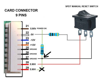
Diagram correctly done is like this:
positive 5V through a 470 ohm resistor to limit current to power good signal when held low and is pulled high when switch is open. And a switch between Power good to ground through 10 ohms resistor. This switch grounds the power good signal when switch is on. That it.
Resistors are there to prevent excessive current and good idea to have cheap resistor burn out if there's a accident than the hard to replace chipset.
Another way:
Power good grounded via 220 ohms resistor to ground. Momentary push button between power good and 5V supply via a 100 ohms resistor. Turn on the PC and push the button once to reset the computer. Also serves as reset button too.
Cheers,
Great Northern aka Canada.