VOGONS


First post, by Snookeroo

User metadata
Rank Newbie
Rank
Newbie

Greetings Vogons. I reach out now in desperate need of your assistance!

A few weeks ago I decided to build my first ever retro rig. I have been really enjoying the process and am at the point where I am beginning to assemble everything in the case I have chosen.

My problem is that I am really struggling to connect the front i/o cables for my case (pwr, reset, hdd led etc). I have been searching everywhere online for a pdf of the manual for my motherboard, but alas, my attempts so far have been in vein, and this is really starting to wedge a wrench into the proceedings!

I would really appreciate any help or suggestions that anyone can provide. Here are all the details I can give:

Case: Old Pentium 3 era Ipex case from Austraila. Same as used in this youtube video:
https://www.youtube.com/watch?v=Jc0jA58LpGk&a … annel=ScanLines
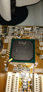
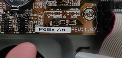
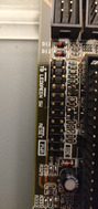
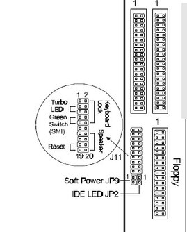
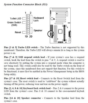
Motherboard: P6Bx-An socket 1 (see pics mobo1, mobo2)
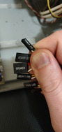
Pic of the front io pins: See pic frontio1
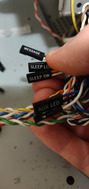
Pics of the front io cables: See pics frontiocables1, frontiocables2

I hope there is someone who can swoop in and save me. My new Win98 retro gaming PC and I would be very grateful!

My apologies if this post is out of place in any way. Please let me know if there is a more appropriate board or something.

Thanks in advance for the assistance.

Attachments

  • mobo2.jpg
    Filename
    mobo2.jpg
    File size
    523.41 KiB
    Views
    312 views
    File license
    Public domain
  • mobo1.jpg
    Filename
    mobo1.jpg
    File size
    1.53 MiB
    Views
    312 views
    File license
    Public domain
  • frontiocables2.jpg
    Filename
    frontiocables2.jpg
    File size
    1.08 MiB
    Views
    312 views
    File license
    Public domain
  • frontiocables1.jpg
    Filename
    frontiocables1.jpg
    File size
    1.45 MiB
    Views
    312 views
    File license
    Public domain
  • frontio1.jpg
    Filename
    frontio1.jpg
    File size
    1.89 MiB
    Views
    312 views
    File license
    Public domain

Reply 1 of 3, by Horun

User metadata
Rank l33t++
Rank
l33t++

It is a Tekram board, the manual for P6BXA has same front panel layout. http://web.archive.org/web/20000303203004/htt … ?Product=P6BX-A
Basically there is two sections: J11 and JP2+JP9. The power switch goes to JP9, the HDD LED goes to JP2 with the red wire on the pin near the I in IDE on the board.
J11 is where you connect the Speaker, Reset and Power LED (to TB LED or Keylock pins 2 and 6). attached pics and link to manual.
Manual: http://www.vogonsdrivers.com/getfile.php?file … 3&menustate=0,0
edit fixed a minor boo-boo

Attachments

  • Image3.jpg
    Filename
    Image3.jpg
    File size
    19.64 KiB
    Views
    293 views
    File license
    Public domain
  • Image5.jpg
    Filename
    Image5.jpg
    File size
    73.29 KiB
    Views
    293 views
    File license
    Public domain

Hate posting a reply and then have to edit it because it made no sense 😁 First computer was an IBM 3270 workstation with CGA monitor. Stuff: https://archive.org/details/@horun

Reply 2 of 3, by Snookeroo

User metadata
Rank Newbie
Rank
Newbie

Ohhhhh, I see now. This is why it was confusing me. I was only looking at the diagram in J11 and wondering why it doesn't match up to the indications which are printed onto the board. Now that I realise it is separated into JP2 and JP9 as well things are much more clear.

Horun, a thousand thank yous for this reply, it really is much appreciated. I'll do a post when my new build is all finished and I'm happily playing Majesty on my Windows 98 PC 😁

Thanks again.

Reply 3 of 3, by Snookeroo

User metadata
Rank Newbie
Rank
Newbie

I have "SLEEP SW" and "SLEEP LED" cables. I'm going to put "SLEEP SW" into "Pins [7 & 9] SMI suspend switch lead", but I'm not sure where to put the "SLEEP LED". Any tips? Thanks guys.