VOGONS


First post, by clb

User metadata
Rank Member
Rank
Member

Hi all,

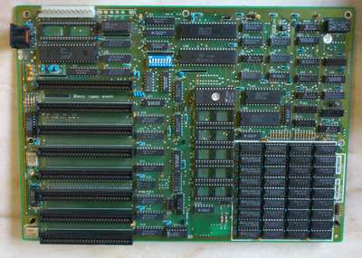
I found this 8088 PC that was stored for a few decades on a shelf of a wooden cabin (out from direct rain and sun exposure, but cold outdoors storage with no insulation, so rain humidity would get in)

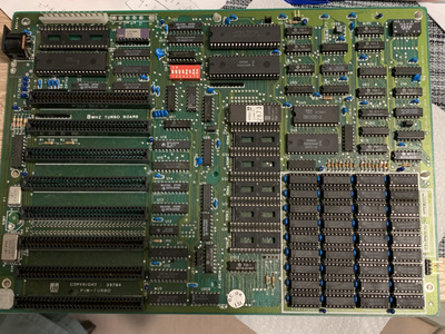
Looking at the board, it has the following markings:

8MHz Turbo Board
Pim-Turbo
Copyright 39784
Rev-5
ERSO/ 1984

I put in a known good 8-bit VGA card, AT keyboard, a PC speaker, IO FDC connector, and booted using a known good AT PSU.

Following the jumpering information at https://jamiestarling.com/project-8088-dtk-pi … 8088-2-jumpers/ , which seems to match this board, I jumpered
- use Color 80x25 board,
- use one attached 5 1/4 drive,
- use 128KB of RAM in bank 0 (to minimize the chances of faulty RAM, though this does not seem like that)

Tried attaching four different floppy drives (two 3.5", two 5 1/4", verified working)

The system boots about 75% of the time, and shows the VGA card BIOS line in 80x25 mode. Upon boot, BIOS line shows

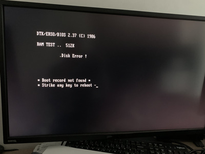
DTK/ERSO/BIOS 2.37 (C) 1986

Just before showing the VGA card line, PC speaker produces six beeps:

long - short - long - short - long - short

Then it does a RAM check, which shows all OK. I have not been able to find what that beep means.

Then, about 90% of that time it boots, it prints ".Disk Error". Sometimes rarely it does not give that error at all. It never tries to boot from the disk. Sometimes the motor of the disk drive does come on, but even if a disk is inserted, it won't boot.

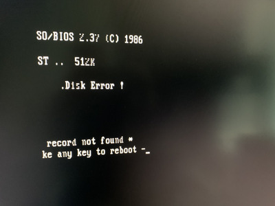
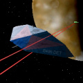
Then there is a text "Boot record not found. Strike any key to reboot" (as shown in IMG_1763.jpg), but pressing a key does not help, the system is not reacting to the keyboard. After a few seconds, the text on the screen will always become corrupt in the same way, as show in the screenshot IMG_1765.jpg. (some of the text chars vanish, and individual scanlines disappear from the rest of the glyphs)

About 25% of the time, the system does not boot at all even, but gives a black screen, no beeps.

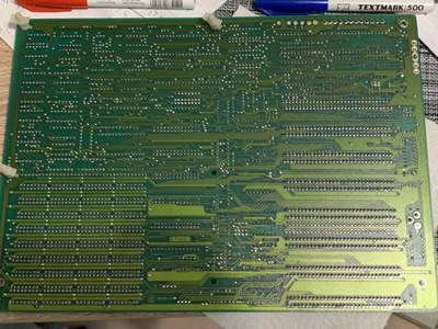
I've cleaned the board with IPA, there was some mild green battery acid style corrosion in the middle of the board next to the ISA slots, from an external card with battery having leaked on top of the board. But after cleaning it all looks moderately clean, does not look like there would be damage to the traces (that I could tell with a brief multimeter continuity testing, though my electronics abilities are not that great).

Tried setting the boards to different ISA slots, but the behavior seems to be the same on each of them.

The caps look good from outside appearance. Tried to measure the capacitance with a multimeter, though I suppose it may not possible when the caps are connected on the board? (I was not getting any reliable/reproducible readings)

Voltages via the test pads next to the PSU are good (which is to be expected, since the PSU is good)

So not sure what to try next. Any thoughts on how one should approach to diagnosing a board like this? I feel like I don't know where to start - I have very little experience with fixing electronics at this level, this might be beyond my abilities. 🙁 Thanks for any guidance!

Attachments

  • IMG_1766.jpg
    Filename
    IMG_1766.jpg
    File size
    1.76 MiB
    Views
    1403 views
    File license
    Public domain
  • IMG_1767.jpg
    Filename
    IMG_1767.jpg
    File size
    1.89 MiB
    Views
    1403 views
    File license
    Public domain
  • IMG_1765.jpg
    Filename
    IMG_1765.jpg
    File size
    1.34 MiB
    Views
    1403 views
    File license
    Public domain
  • IMG_1763.jpg
    Filename
    IMG_1763.jpg
    File size
    1.27 MiB
    Views
    1403 views
    File license
    Public domain

Reply 1 of 29, by zapbuzz

User metadata
Rank Oldbie
Rank
Oldbie

being non plug and play you'd need to plug disk controllers in each port to find the pre programmed correct one same as other cards it could be looking for memory expanson comms hard disk tape etc. If possible try find someone to dump your boards bios to tell you whats in it i bet a museum technician could help.
An ordinary technician can dump it too but I recommend dumping it to preserve it in case because that bios is so damn old.
I don't know but maybe theres diskettes with cmos tools to change things.
Beep codes can be anything but usually its trying to hook up to something like a monochrome video controller card, expanded memory card, hard disk card etc.
System board memory could be malfunctioning but that would only be proven with a donor boards memory contents installed thats known good or knowlege of testing for faulty chips..
A SCSI controller with a pre installed hard disk with correct dos would help boot it because SCSI has its own bios and just may boot after other controller methods fail to give a boot.
This is really something I would sell that the buyer wuld have the stuff for it. Buying a complete system would be the goal of selling this for me that is takes up good amount of the price then theres no guess the config. man all those unused bios sockets.
I see a few of this board on ebay today there are sites out there with bios but these old non plug and play are like each to their own.
I had an XT clone one it was horrible i dunno if this is an XT ....
here is a link i found shows dip switch info about memory etc https://jamiestarling.com/project-8088-dtk-pi … 8088-2-jumpers/

I think those little capacitors for the ram banks could be replaced but thats just me.

Last edited by zapbuzz on 2021-07-19, 15:47. Edited 1 time in total.

Reply 2 of 29, by BitWrangler

User metadata
Rank l33t++
Rank
l33t++

So I'd get a brown paper, kraft paper bag, get it folded twice (four thicknesses of paper, if you're using an edge of the bag rather than having it opened out, you've got one fold already there) then surface wet that both sides with IPA and shove it in and out of 3 of the middle slots. Sometimes need some slight abrasiveness to shift stubborn oxides. Then wipe your card edges with it too, then put them in those clean slots and retry, if it works now, do the rest.

Unicorn herding operations are proceeding, but all the totes of hens teeth and barrels of rocking horse poop give them plenty of hiding spots.

Reply 3 of 29, by zapbuzz

User metadata
Rank Oldbie
Rank
Oldbie
BitWrangler wrote on 2021-07-19, 15:47:

So I'd get a brown paper, kraft paper bag, get it folded twice (four thicknesses of paper, if you're using an edge of the bag rather than having it opened out, you've got one fold already there) then surface wet that both sides with IPA and shove it in and out of 3 of the middle slots. Sometimes need some slight abrasiveness to shift stubborn oxides. Then wipe your card edges with it too, then put them in those clean slots and retry, if it works now, do the rest.

hey yeah that first - i should have thought of it

Reply 4 of 29, by mkarcher

User metadata
Rank l33t
Rank
l33t
clb wrote on 2021-07-19, 14:15:
I put in a known good 8-bit VGA card, AT keyboard, a PC speaker, IO FDC connector, and booted using a known good AT PSU. […]
Show full quote

I put in a known good 8-bit VGA card, AT keyboard, a PC speaker, IO FDC connector, and booted using a known good AT PSU.

[...]

Following the jumpering information at https://jamiestarling.com/project-8088-dtk-pi … 8088-2-jumpers/ , which seems to match this board, I jumpered
- use Color 80x25 board,
- use one attached 5 1/4 drive,
- use 128KB of RAM in bank 0 (to minimize the chances of faulty RAM, though this does not seem like that)

It's not the cause of your issue, but you are not supposed to jumper "Color 80x25" unless you use an actual CGA card. The mainboard BIOS has an integrated CGA and MDA video BIOS. The DIP switches are supposed to mean:

  • Color 40x25: Use integrated CGA BIOS, boot in 40x25 mode (mode 1)
  • Color 80x25: Use integrated CGA BIOS, boot in 80x25 mode (mode 3)
  • Mono 80x25: Use integrated MDA BIOS, boot in 80x25 mode (mode 7)
  • EGA/PGA/VGA: Do not use the integrated video BIOS, use BIOS from a separate video card instead

Most mainboard BIOSes auto-probe for the presence of the selected video card (for CGA and MDA settings), and if you do not have that card, but you do have the other card, they disobey the switches and force Color 80x25 or Mono 80x25. Also, most mainboards initialize the video BIOS (at C000) even if you don't configure "EGA/PGA/VGA", and the video BIOSes make the system work regardless of the switches. It's better to follow documented rules, though, especially if using EGA cards.

If you have both an MDA and a CGA card installed, the DIP switches select which video card is used at boot. If you combine the EGA with a secondary video card (either EGA / mono monitor + CGA card or EGA / color monitor + MDA card), you are supposed to set the mainboard switches to EGA all the time, no matter what card you want to be the primary or secondary video card. Instead, you select the primary video card using the DIP switches on the EGA card instead. The EGA BIOS handles the activation of the mainboard CGA BIOS or mainboard MDA BIOS at boot if the EGA card is secondary or on demand if a program selects a mode that is provided by the non-EGA card.

Reply 5 of 29, by Errius

User metadata
Rank l33t
Rank
l33t

I have one of these boards. I believe this is the manual: http://www.minuszerodegrees.net/manuals/Turbo … ion%20Guide.pdf

ETA: Added picture of my board

Attachments

  • PIM-TURBO.jpg
    Filename
    PIM-TURBO.jpg
    File size
    1 MiB
    Views
    1331 views
    File license
    Public domain

Is this too much voodoo?

Reply 6 of 29, by clb

User metadata
Rank Member
Rank
Member
BitWrangler wrote on 2021-07-19, 15:47:

So I'd get a brown paper, kraft paper bag, get it folded twice (four thicknesses of paper, if you're using an edge of the bag rather than having it opened out, you've got one fold already there) then surface wet that both sides with IPA and shove it in and out of 3 of the middle slots. Sometimes need some slight abrasiveness to shift stubborn oxides. Then wipe your card edges with it too, then put them in those clean slots and retry, if it works now, do the rest.

Great suggestion! I did use IPA with a toothbrush to go through the slots really close, but that did probably not do much at all.

Oxidation of the ISA slots certainly seems to play a role. If I switch the VGA card around, it has trouble producing an image in half of the slots. I wonder if there would exist replacement slot connectors that I could get and resolder those in there for brand new ones instead... I'll look around, maybe some cheap faulty mobo could serve as a donor.

Reply 7 of 29, by clb

User metadata
Rank Member
Rank
Member
mkarcher wrote on 2021-07-19, 17:06:
It's not the cause of your issue, but you are not supposed to jumper "Color 80x25" unless you use an actual CGA card. The mainbo […]
Show full quote

It's not the cause of your issue, but you are not supposed to jumper "Color 80x25" unless you use an actual CGA card. The mainboard BIOS has an integrated CGA and MDA video BIOS. The DIP switches are supposed to mean:

  • Color 40x25: Use integrated CGA BIOS, boot in 40x25 mode (mode 1)
  • Color 80x25: Use integrated CGA BIOS, boot in 80x25 mode (mode 3)
  • Mono 80x25: Use integrated MDA BIOS, boot in 80x25 mode (mode 7)
  • EGA/PGA/VGA: Do not use the integrated video BIOS, use BIOS from a separate video card instead

Thanks! I rejumpered switches 5 and 6 to ON state ("Type of Display - None" according to http://www.minuszerodegrees.net/manuals/Turbo … ion%20Guide.pdf. That works, still get the VGA image, and the "long - short - long - short - long - short" beep POST code is now gone! So looks like that was the cause of that BIOS POST beep.

Reply 8 of 29, by mkarcher

User metadata
Rank l33t
Rank
l33t
clb wrote on 2021-07-19, 18:34:

Thanks! I rejumpered switches 5 and 6 to ON state ("Type of Display - None" according to http://www.minuszerodegrees.net/manuals/Turbo … ion%20Guide.pdf. That works, still get the VGA image, and the "long - short - long - short - long - short" beep POST code is now gone! So looks like that was the cause of that BIOS POST beep.

So I was partly wrong about "It's not the cause of your issue". And your reply reminded me that I have a DTK BIOS disassembled at hand. Indeed, 3x (long-short) is expected for "video card/configuration error". The DTK BIOS performs some basic tests of the CGA card that is supposed to be present before it calls the VGA card BIOS to initialize the VGA card. Obviously, your VGA card needs some basic initialization before it behaves similar enough to a CGA card so that it would pass the CGA POST. This is nothing wrong about your VGA card - it is perfectly valid for VGA cards to not respond properly to CGA or MDA like bus cycles until initialized.

If you configure "Type of Display - None", the complete video intialization/self-test section of the mainboard BIOS is skipped, and the BIOS goes straight on to call the VGA BIOS to initialize the VGA card.

Reply 9 of 29, by clb

User metadata
Rank Member
Rank
Member
Errius wrote on 2021-07-19, 17:09:

I have one of these boards. I believe this is the manual: http://www.minuszerodegrees.net/manuals/Turbo … ion%20Guide.pdf

ETA: Added picture of my board

Really great to hear - I hope you may be lurking around in case I need help cross-referencing something.

Actually, got some progress now! I was able to boot to a MFM hard drive - once. Attaching a MFM hard drive connector and a ST-225 hard disk to the topmost slot let the system boot. Though most of the sectors on that disk seem to be corrupted and unable to read - but it did boot to DOS.

I am still unable to get a floppy disk working. There were two floppy disk drives, a 5 1/4" and a 3.5" one. They were connected to a IO board on the same cable - rejumpered to use a single drive, and try to boot from it. Switched different drives around, and trying to figure out if anything would work - but so far I always get a Disk Error. Oddly in order to boot from hard drive, it looks like I need a floppy disk device attached, or POST will hang. (at least that is my impression so far)

trying out the 5 1/4" drive on another known working 386 PC, it looks like the drive is bad, and eats floppies, producing visual scratches on them. Trying out another floppy drive, but no much help.

Do you know if there would be anything special with the ISA IO boards for a 8088 specifically? I have another ISA IO board that I have been trying in case the original one could be oxidized, but that does not seem to help.

If I do "format A: /S" on a 386 DOS 6.22 system, should that be able to boot on a 8088 just fine?

I wonder given that I was able to boot once, if I should get an XT-IDE or something like that? ( https://www.glitchwrks.com/2017/11/23/xt-ide-rev4 ) Maybe that would improve stability in case the MFM hard drive controller itself has gotten flaky over time - rather than think about getting a new MFM hard drive.. (Although I wish I'd be able to get this running without a hard drive at all just from a floppy beforehand to make sure that path is solid)

Reply 10 of 29, by mR_Slug

User metadata
Rank Member
Rank
Member

You mention you stuck an AT keyboard in it. It's an XT so needs an XT keyboard. Check if your keyboard has an XT switch on the bottom of it. You'll get nothing out of an XT with an AT keyboard. No idea what the beep codes mean, could be keyboard, could be RAM. The few DTK BIOS board I've dealt with do a RAM count *then* display an image. Why they did this I have no idea but I though the board was dead until I waited for a while.

format A: /S on any system will work. But make sure the floppy is 360K or 720K. XT's won't do 1.44 or 1.2MB.

The Retro Web | EISA .cfg Archive | Chip set Encyclopedia

Reply 11 of 29, by Errius

User metadata
Rank l33t
Rank
l33t

Earlier thread about the same board: Retrofanatic's "8Mhz TURBO BOARD" NEC V20 XT Build

I tested mine with a VGA card, MFM drive and 5.25"/3.5" floppy drives. POSTs fine but only small programs (like DOS commands and small .COM games) run correctly. Larger programs malfunction/crash. Almost certainly a faulty RAM chip which I need to identify and reseat/replace.

Be aware that you need a high density floppy drive controller to read 1.44 MB/1.2 MB HD disks. Even if you have a HD drive, it will not read HD disks without such a controller. (It will just function as a DD drive.) What floppy controller do you have?

Is this too much voodoo?

Reply 12 of 29, by mkarcher

User metadata
Rank l33t
Rank
l33t
Errius wrote on 2021-07-19, 19:09:

Be aware that you need a high density floppy drive controller to read 1.44 MB/1.2 MB HD disks. Even if you have a HD drive, it will not read HD disks without such a controller. (It will just function as a DD drive.)

You do not only need a high density floppy controller (which you could find on any AT multi-I/O card), you also need BIOS support for the HD controller/drive. The standard ERSO/DTK BIOS does not support HD controllers or drives, so to boot from an HD floppy, you would need a floppy controller with a BIOS extension to support high density drives. I don't know whether such cards exist, but I wouldn't be surprised if they did.

Reply 13 of 29, by clb

User metadata
Rank Member
Rank
Member
mR_Slug wrote on 2021-07-19, 19:05:

You mention you stuck an AT keyboard in it. It's an XT so needs an XT keyboard. Check if your keyboard has an XT switch on the bottom of it. You'll get nothing out of an XT with an AT keyboard. No idea what the beep codes mean, could be keyboard, could be RAM. The few DTK BIOS board I've dealt with do a RAM count *then* display an image. Why they did this I have no idea but I though the board was dead until I waited for a while.

Sorry, I think now that I miswrote. I was not aware of the AT/XT distinction before, looked it up now. When I wrote "AT" before, I referred to just the AT connector - I've known that 5-pin DIN connector under the "AT connector" name, but now I see that both AT and XT keyboards use the same connector.

I tried using the original keyboard that the computer was stored with, a "Data Comp" manufactured Model F style keyboard. That worked partially, but many keys don't register - probably need to open and clean it up. I then replaced that with an IBM Model M keyboard, which did work properly. I suspect these both are XT keyboards. (the IBM Model M works on another 386 computer from 91/92, so I believe it would have to be XT and not an AT?)

Reply 14 of 29, by clb

User metadata
Rank Member
Rank
Member
mkarcher wrote on 2021-07-19, 19:52:
Errius wrote on 2021-07-19, 19:09:

Be aware that you need a high density floppy drive controller to read 1.44 MB/1.2 MB HD disks. Even if you have a HD drive, it will not read HD disks without such a controller. (It will just function as a DD drive.)

You do not only need a high density floppy controller (which you could find on any AT multi-I/O card), you also need BIOS support for the HD controller/drive. The standard ERSO/DTK BIOS does not support HD controllers or drives, so to boot from an HD floppy, you would need a floppy controller with a BIOS extension to support high density drives. I don't know whether such cards exist, but I wouldn't be surprised if they did.

Thanks, maybe this is the critical bit why I am failing to attach a floppy drive. All of the 3.5" and 5 1/4" drives I've tried are HD drives, and I believe the extra IO controller I've been trying is a HD controller, so maybe that is why it insists on giving a Disk Error on boot - wanting to see a DD drive + controller.

You say a HD drive would function as a DD drive - so if I attach a HD drive to a DD controller, should that make the drive behave like a DD drive? Is there a way for the BIOS to detect any difference? I wonder if it could be the cause of the Disk Error. I'll try cleaning some more contacts on the boards in case that would help.

Reply 15 of 29, by Errius

User metadata
Rank l33t
Rank
l33t

Yes, my machine came to me with a YD-701B 3.5" drive, which is HD, and which I assume was added by the previous owner. However he kept the original XT controller card, so this drive just worked with 720 KB disks and did not recognize 1.44 MB disks.

Is this too much voodoo?

Reply 16 of 29, by Errius

User metadata
Rank l33t
Rank
l33t
zapbuzz wrote on 2021-07-19, 15:07:

This is really something I would sell that the buyer wuld have the stuff for it. Buying a complete system would be the goal of selling this for me that is takes up good amount of the price then theres no guess the config. man all those unused bios sockets

I believe these are for ROM BASIC. When upgrading a PC or XT with this board you were supposed to remove the BASIC ROMs from the original IBM board and put them in those sockets. However by this time (mid-late 1980s) nobody was using BASIC for serious work anymore so most upgraders didn't bother to transfer the chips.

Is this too much voodoo?

Reply 17 of 29, by zapbuzz

User metadata
Rank Oldbie
Rank
Oldbie
Errius wrote on 2021-07-20, 08:20:
zapbuzz wrote on 2021-07-19, 15:07:

This is really something I would sell that the buyer wuld have the stuff for it. Buying a complete system would be the goal of selling this for me that is takes up good amount of the price then theres no guess the config. man all those unused bios sockets

I believe these are for ROM BASIC. When upgrading a PC or XT with this board you were supposed to remove the BASIC ROMs from the original IBM board and put them in those sockets. However by this time (mid-late 1980s) nobody was using BASIC for serious work anymore so most upgraders didn't bother to transfer the chips.

The thing about basic is it was the gatewqay to many many assembly coders from childhood assembly will never go obselete it is the hardest and most low level language.

Reply 18 of 29, by mkarcher

User metadata
Rank l33t
Rank
l33t
Errius wrote on 2021-07-20, 07:58:

Yes, my machine came to me with a YD-701B 3.5" drive, which is HD, and which I assume was added by the previous owner. However he kept the original XT controller card, so this drive just worked with 720 KB disks and did not recognize 1.44 MB disks.

It's not that easy. There is a density select pin on the floppy cable, the repurposed "reduced write current" pin. On IBM PC compatible floppy systems, this pin needs to be pulled low by the controller card if the drive is to operate in DD mode. The drive input is TTL, so if the pin is left open, it will be interpreted high, which selects HD mode. Whether this matters at all is highly dependent on the drive, though. Some drives switch analog filtering depending on this pin. For example, I have a drive that can write DD disks in a way that other drives can read them, and can read DD disks written by other drives, but can not read DD disks it wrote itself if you leave this pin high. It can read the DD disks it writes if you pull the pin low.

So if you want to connect an HD drive to a DD controller, you might need to pull pin 2 low, or jumper/switch it into DD only mode. I suppose the original IBM DD controller, and a lot of clones, let pin 2 float high.

Reply 19 of 29, by Errius

User metadata
Rank l33t
Rank
l33t

That's interesting, I never encountered compatibility problems. I have a stack of blue ex-Amiga DD disks which I use in these situations.

I also remember that the power cable of the 3.5" drive was directly soldered to the power contacts of the 5.25" drive. Presumably this was also done by the previous owner. I guess Molex to Berg adaptors weren't a thing back then.

Is this too much voodoo?