VOGONS


First post, by Snookeroo

User metadata
Rank Newbie
Rank
Newbie

Greeting Vogons,

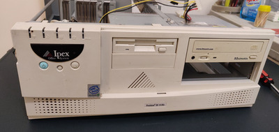
I am assembling a super cool Windows 98 gaming PC inside an old Ipex Pentium 3 case. I'm unable to find any information regarding the model number of the case, but it's the same one featured in this video:
https://www.youtube.com/watch?v=Jc0jA58LpGk&t … annel=ScanLines

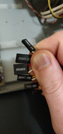
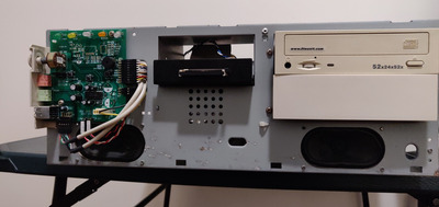
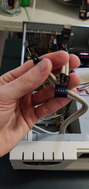
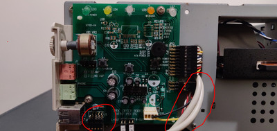
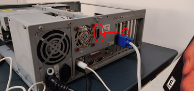
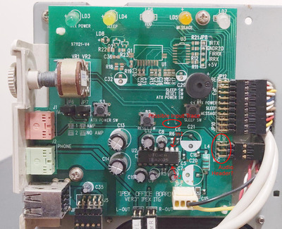
The case has built-in speakers (see them in the bottom corners in bare_front.jpg) and I would really like to get them working since it would save me some space and money on external ones. There is a 4-pin front io header labelled "speakers", which I have tried plugging in to the front-io pins on my motherboard marked for speakers. Unfortunately no matter how I orientate the pins on the header, the speakers don't seem to do anything.

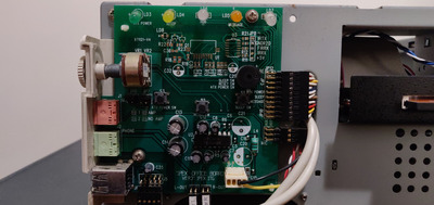
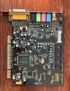
Would it be possible to plug these speakers in to my Sound Blaster Live 5.1 somehow? I would love to have all of my audio coming through them if possible.

Thanks in advance for all the help and guidance, my venerable Vogons!

Cheers,
Snookeroo.

Attachments

  • frontiocables1.jpg
    Filename
    frontiocables1.jpg
    File size
    1.45 MiB
    Views
    977 views
    File license
    Public domain
  • front_io_board.jpg
    Filename
    front_io_board.jpg
    File size
    1.56 MiB
    Views
    977 views
    File license
    Public domain
  • case1.jpg
    Filename
    case1.jpg
    File size
    1.41 MiB
    Views
    977 views
    File license
    Public domain
  • bare_front.jpg
    Filename
    bare_front.jpg
    File size
    1.36 MiB
    Views
    977 views
    File license
    Public domain

Reply 1 of 22, by wiretap

User metadata
Rank Oldbie
Rank
Oldbie

What other headers do you have available? That 4-pin speaker header appears to be for the PC-speaker. You'll want to find a set of 4 wires for the speakers -- L+/L- and R+/R-. Or possibly 3.5mm audio plugs that are supposed to pass through a PCI slot and plug into the sound card.

My Github
Circuit Board Repair Manuals

Reply 2 of 22, by Snookeroo

User metadata
Rank Newbie
Rank
Newbie

I can see where the L+/L-, R+/R- wires are plugged in to the front io board. I could detach them and put them in to my sound card perhaps, but where would I plug them in?

My sound card is a Sound Blaster Live! 5.1 Digital, model SB0220. I have attached a picture.

Thanks again for the help.

Attachments

Reply 3 of 22, by wiretap

User metadata
Rank Oldbie
Rank
Oldbie

The speaker L/R at the bottom of that front panel board I assume go to the speakers themselves. You'll want to find the input, not the output. Then on the Sound Blaster, you can utilize the white pin socket to feed the audio to them. (pins 2 and 4 are for analog headphone output)

My Github
Circuit Board Repair Manuals

Reply 4 of 22, by Snookeroo

User metadata
Rank Newbie
Rank
Newbie

So something like this? I could buy one of those adapters, but I'm not sure where I'd connect it 😒
SB Live 5.1 Digital Front Panel Connector

Reply 5 of 22, by Snookeroo

User metadata
Rank Newbie
Rank
Newbie

There aren't any headers marked "audio" or anything similar. All I can find is this one which I thought had something to do with the USB ports. I have circled it in the pictures attached. It goes into this grey cable which routes along a strut to this large output at the back of the case.

Any clues?

Attachments

Reply 6 of 22, by LewisRaz

User metadata
Rank Member
Rank
Member

You need to get a 3.5mm patch/aux cable from the green output of your soundcard to the green input on the back of the case. Like you can see here: https://youtu.be/CjCqjFEsRUg?t=485

My retro pc youtube channel
Twitter

Reply 7 of 22, by Snookeroo

User metadata
Rank Newbie
Rank
Newbie
LewisRaz wrote on 2021-08-04, 08:19:

You need to get a 3.5mm patch/aux cable from the green output of your soundcard to the green input on the back of the case. Like you can see here: https://youtu.be/CjCqjFEsRUg?t=485

That's amazing! How have I not seen this video before?!

So I would need some sort of adapter for this input? It certainly runs to the front io card.

Attachments

Reply 8 of 22, by Snookeroo

User metadata
Rank Newbie
Rank
Newbie

After a bit more research I have concluded that speakers are accessed through this port at the back, which seems to be a db15 "joystick" or "game" port. My soundcard has a MIDI/Joystick output in this configuration, so maybe if I get a male to female db15 game port pass through cable then I can connect the sound card to the speakers and it will work?! Does this sound right?

Reply 9 of 22, by snufkin

User metadata
Rank Oldbie
Rank
Oldbie

There's no audio on the 15 pin gameport pinout on the soundcard, so the 15 pin connector on the back of the case is probably something custom. I think you need to find which pins on the connector go to pins 7 and 10 on that TEA2025 chip. Those are the inputs to the amplifier:
http://www.unisonic.com.tw/datasheet/TEA2025.pdf.

The connection might go via that 3x2 header that says 'MIC' just beneath it, and also the volume control VR1 & VR2. You might be able to trace the connections by looking at the pcb traces, but if you have access to a multimeter it'll be easier.

If you can find a connection between those 2 pins and the 15 pin connector, then you'll need to make up a custom 3.5mm stereo -> 15 pin dsub cable. It'd be interesting to know what else is on that connector. I'd guess the Mic input goes there as well, but 15 pins seems a bit big for just a stereo output and a mono input.

[edit - I've marked up where I think the audio inputs on that front board are. I'm wondering if there used to be a breakout cable for that 15 pin connector to get back panel USB & Audio to the front panel. 15 pins would be a good number for 2 USB ports and audio in/out.]

Attachments

Reply 10 of 22, by Snookeroo

User metadata
Rank Newbie
Rank
Newbie

I had to read your post a few times, but I think I get what you mean now. I'm no electrical engineer, but I agree that it looks like the 3x2 is receiving all the audio stuff.

The 15-pin connector definitely gives USB, and I have reason to believe that it's for stereo as well, since all the cables from that 3x2 go into group which goes into the 15-pin as well. There isn't a single other header in the whole chassis either which mentions audio, so this has to be it.

I don't know if I'd have the know-how to build my own 3.5mm stereo -> 15 pin dsub adapter. I suppose Ipex probably sold them along with these machines back in the day, and it would have just had a 3.5mm input on there which you would passthrough your soundcard to. I'll take a look around online and see if any such thing exists, otherwise I might just pop it in the too-hard basket and buy myself some external speakers.

Huge thanks to everyone for all the help and suggestions. It always warms my heart to be saved by an intelligent Vogon!

Reply 12 of 22, by Snookeroo

User metadata
Rank Newbie
Rank
Newbie

I thought about buying it, but it will cost me $50 and take over a month to arrive... also I don't know if it would even work. If I knew for sure that it would connect up and the front audio would all work like a dream, then maybe I would, but I'm not paying $50 for a bet which I'll have to wait a month to see the result on.

On the other hand, I've found a perfectly good pair of external speakers for only $10 on Gumtree, so I think I'll set this to rest and go with those.

Reply 13 of 22, by LewisRaz

User metadata
Rank Member
Rank
Member
Snookeroo wrote on 2021-08-07, 13:50:

Do you think something like this could do the job?
https://www.ebay.com/itm/15-Pin-D-Sub-2-row-G … d-/393033481804

Thats alot of money for something that has a high chance not to work.

I Imagine Ipex had their own breakout cable but a quick search of ebay did not find anything

My retro pc youtube channel
Twitter

Reply 15 of 22, by wiretap

User metadata
Rank Oldbie
Rank
Oldbie

You can make one. Just get a DB15 shell with the solder cups. You can use a multimeter to trace the pins back to the front circuit board. Then you can solder on the 3.5mm cable with a short pigtail.

My Github
Circuit Board Repair Manuals

Reply 17 of 22, by Warlord

User metadata
Rank l33t
Rank
l33t

this thread is confusing to go through.
Basically what you need is a multimeter that can do continuity. You can get a multimeter at almost any hardware store.

All you need to do is set the multimeter to continuity. Touch one probe to the speak left or right and, touch the other probe to the rear db15 connector pin and probe till it rings.. When you hear a ringing you have continuity and thats how you trace it. Once you figure out each pin, get a blank db 15 connector and a male to male 3.5 cable. Cut the cable and solder the wires to the plug. Its easy peasy.

Reply 18 of 22, by canthearu

User metadata
Rank Oldbie
Rank
Oldbie
Warlord wrote on 2021-08-07, 19:44:

this thread is confusing to go through.
Basically what you need is a multimeter that can do continuity. You can get a multimeter at almost any hardware store.

All you need to do is set the multimeter to continuity. Touch one probe to the speak left or right and, touch the other probe to the rear db15 connector pin and probe till it rings.. When you hear a ringing you have continuity and thats how you trace it. Once you figure out each pin, get a blank db 15 connector and a male to male 3.5 cable. Cut the cable and solder the wires to the plug. Its easy peasy.

Won't be that simple since there is likely an amplifier for the speakers.

But that side, I can probably sill work it out if nobody here is able to.