First post, by Kahenraz

- Rank
- l33t
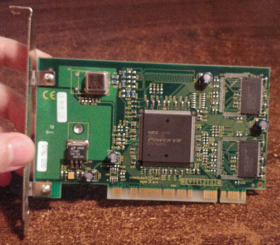
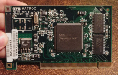
I would like to experiment with overclocking the PowerVR PCX2 by replacing the onboard quartz crystal. But this accelerator already gets too hot to touch even at its natural 66Mhz clock. To do this safely I would need to attach a heatsink, preferably with a fan on it.
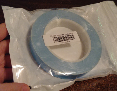
I have some thermal tape already but its adhesion is not always reliable depending on the weight applied to it. And its thermal conductivity is functional but can end up acting as an insulator if the temperature is too high. For example, I tested this tape vs some generic thermal compound on a Celeron D with an excellent Zalman heatsink. With the tape the CPU reached nearly 90C when monitoring in the BIOS but less than 50C with generic paste.
This suggests that the usefulness of thermal tape is limited useful at high temperatures. There may be better tape; but this is the only kind I have.
While thermal epoxy (and regular epoxy) is already available, I would like to use regular, quality thermal paste and instead drill some holes into the PCB for mounting points.
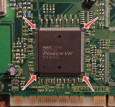
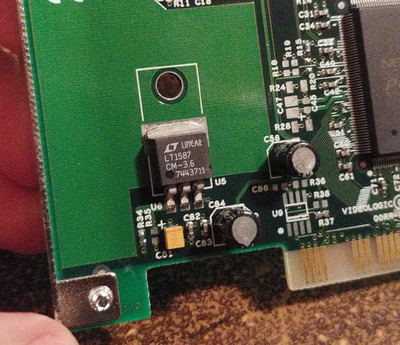
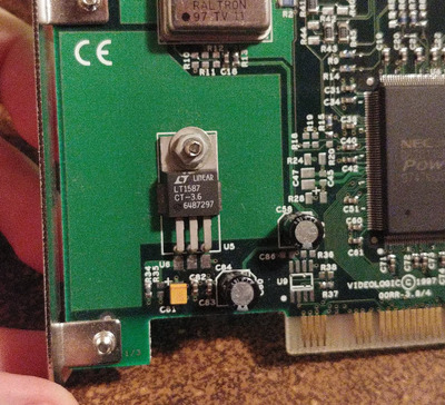
The danger in this is that I don't know what's in the PCB if multiple layers exist. There appear to be four spots around the accelerator chip that would be adequate but it might not be safe. These circles are present on the top of the PCB but not on the bottom, furthering the mystery.
=https://www.youtube.com/watch?v=fjUscS ... reat video where they talked about the dangers of a short circuit that can occur when traces are bridged within a PCB due to design error. Some probing tells me that the silver area at the center of these circles suggests that it is not connected to the ground plane and may just be plated on the surface.
For safety, I would like to have the board x-rayed so that I can know for sure if drilling holes into these places would he safe. Does anyone have access to or know someone who can photograph this PCB to find out?