VOGONS


First post, by Vipersan

User metadata
Rank Oldbie
Rank
Oldbie

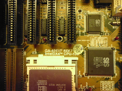
A short time ago I aquired a GA-486VF rev 7 in a very sorry non working state ..
It was bare bones and had suffered some really bad battery corrosion ..along an inch strip at the edge of the pcb.
I knew it would be a challenge ..but had to at least try.
Some of the traces were simply not there in places ..dissolved.
But I added wire links topside following the traces original paths.
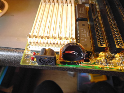
I also replaced 2 electrolytic capacitors which were bloated and the plastic sleeves shrunk.
330uf at 16v
I also had to remove the psu connector to work and clean underneath it.
Next ..a new 5 pin keyboard connector din ...some pins had dissolved inside the original.
OK the last hurdle physically was to replace the varta battery (already removed) with vertically mounted 2032 coin cell and series diode.
All this can be seen in the photos.
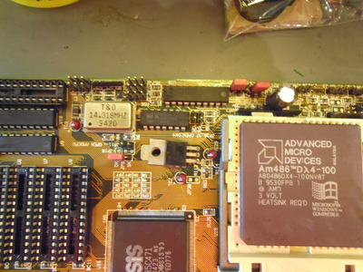
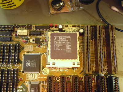
The only cpu I have which hopefully is suitable is an AMD 486-DX-100
..but there are so many jumpers it is more than a bit confusing ..and they were all missing.
So far I have fitted 3 which again can be seen in the photos as they are Red.
So at this point I just want to establish if it works.
I have powered up with no CPU ...no ram and chips missing which presumably are Cache.
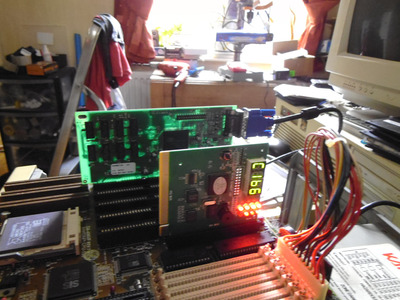
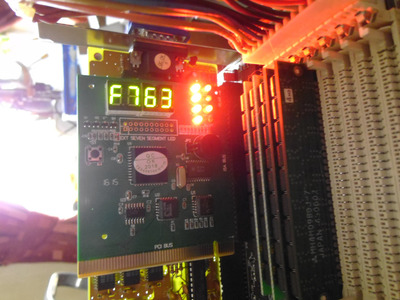
...and a post/diagnostic card in the 8 bit ISA slot..
All supplies appear to be present and correct ...and the cpu clock led does light up.
..but I dont want to power up with the cpu fitted until someone else take a look..hopefully one of you guys is familliar with this ISA/VLB mobo ?
please check the photos.
There may well be other issues with this board ...but I gotta start somewhere.
rgds
VS

There were other issues with this motherboard.....which refused to boot a few hours after nailing the problem regarding not able to comlete boot and drive a video card..
That fault was eventually traced to a faulty from new POST diagnostic card which was grounding bit 3 of the ISA bus.
The POST card was eventually repaired ...details are on pages 7 snd 8 of this thread ...

After Several hours of running the motherboard refused to even start up ..
This fault was eventually tracked down to L1
A brief summary of this -
Basically the fault (in short) was traced to an open circuit or very high resistance ferrite chip surface mount inductor.
Other ascociated components have already or will be changed in the near future.
This inductor is responsible for the 5v supplies to the clock processing/generation IC for the CPU ...so no clock ..no startup ...and the cpu remains in reset.

So the mobo was eventually fixed...but still misidentifies the DX4-100 CPU at boot
This is yet to be solved.
For anyone interest the Bios dump from this board is on this page...a bit lower down.

The thread jumps about a bit so on advice I've edited this first post...and next time I will start a new thread before switching topics mid stream.
rgds
VS

Attachments

  • P1000733.JPG
    Filename
    P1000733.JPG
    File size
    1.04 MiB
    Views
    1706 views
    File license
    Fair use/fair dealing exception
  • P1000731.JPG
    Filename
    P1000731.JPG
    File size
    778.11 KiB
    Views
    1706 views
    File license
    Fair use/fair dealing exception
  • P1000730.JPG
    Filename
    P1000730.JPG
    File size
    1.22 MiB
    Views
    1706 views
    File license
    Fair use/fair dealing exception
  • P1000729.JPG
    Filename
    P1000729.JPG
    File size
    805.66 KiB
    Views
    1706 views
    File license
    Fair use/fair dealing exception
Last edited by Vipersan on 2021-10-05, 13:09. Edited 1 time in total.

Reply 1 of 165, by Eep386

User metadata
Rank Member
Rank
Member

According to this...
http://www.motherboards.org/files/manuals/47/486vs8a.pdf

You'll want to close JP5, JP6 and JP7 with jumper caps to set a 33MHz system bus. Currently those three are open so the resulting clockrate may be undefined.
If you set the wrong speed, it's not likely anything will get damaged, it'll just not work or not work as you'd expect. But I'd still close them anyway.
As a precaution though, fit a heatsink to that CPU before turning the board on. Even the 3.3V 486s tend to run quite furiously hot for vintage computer pieces.

CPU voltage jumpers (JP36, JP37) look okay as-is for that CPU. You've got an AMD DX4-100, a 3.3V CPU, so leaving those jumpers open will run it at 3.3V. Closing them will run the CPU at 5V... not a good thing to do to a 3.3V CPU.

The cache chips to put in those empty sockets are 32Kx8 DIP-28 SRAMs, preferably clocked at 15ns or faster. At 33MHz bus speed, you'll need at least 15ns to use the lowest waitstate operation available.

Life isn't long enough to re-enable every hidden option in every BIOS on every board... 🙁

Reply 2 of 165, by Vipersan

User metadata
Rank Oldbie
Rank
Oldbie

Thanks for your guidance Eep..
I've added the 3 extra jumpers as suggested..
Still no ram or cache fitted ...and I didn't power up for long as I dont yet have a suitable heatsink and fan..
But there are signs of life from the post card..
Ive ordered some KM68257CJ-15 ...25 pieces for £13 delivered.
fingers crossed for a good result eventually...but I'm taking this one slowly.
rgds
VS

Attachments

  • P1000734.JPG
    Filename
    P1000734.JPG
    File size
    793.08 KiB
    Views
    1634 views
    File license
    Fair use/fair dealing exception

Reply 3 of 165, by Vipersan

User metadata
Rank Oldbie
Rank
Oldbie

So ..
fitted a small cpu heatsink and a couple of 4mb simm in the first 2 slots.
No change on the post card.
The CPU doesn't get warm.
There may well be more physical damage to the motherboard...but I'm not ready to give up just yet.
I guess it is possible that the bios is corrupt.
My next thought would be to replace the bios.
I could do this by writing it to and eprom ...which wouldn't be that hard.
..but first I would need the bin file.
Does anyone know where I might find this.
a link to an archive of old bios etc would be useful.
?
rgds
VS

Reply 4 of 165, by Vipersan

User metadata
Rank Oldbie
Rank
Oldbie

Looks like I have found a bios dump by Predator99 on the forum.
Re: 80486 BIOS image collection
I'll be flashing a replacement asap..
No guarantee this will help ..but at least I can eliminate it.
rgds
VS

Reply 5 of 165, by mr.cat

User metadata
Rank Member
Rank
Member

It's a different revision though. Idk if that matters.
Make sure you get a backup of the old one (and post it here, please).
It seems these old BIOSes are not available at archive.org's old gigabyte.com.tw mirror but there may be some other places to check.

There's no mention of the B6 code in the manual, but the fact that some codes can be seen means that the CPU works and BIOS code is being executed.
(But ofc it won't get very far without RAM and cache.)
The BIOS can be emulated (in 86Box, for example) for comparison.

EDIT: I ran Predator99's rev.6 binary in emulation (UniPCemu), it seems that one doesn't have the B6 code either. There's BE though, that's only one bit difference.
So I guess that's a hw issue, unless B6 is something rev.7 specific (and even so, that test was passed).

Last edited by mr.cat on 2021-09-01, 14:23. Edited 1 time in total.

Reply 6 of 165, by shamino

User metadata
Rank l33t
Rank
l33t

Use a multimeter and measure the power supply voltages from the PSU. You can put the negative probe on the PSU casing or something else convenient that's likely to have a good connection to ground.
Maybe also measure at some other points on the board, like at the BIOS chip for example, just to see that those voltages are actually reaching the components and not dropping off somehow.
Most DIP chips will have +5V (or whatever) at one corner pin and GND at the opposite corner. That's not universal but it's typical.

Measure the power supply voltage to the CPU socket.
There's probably a pinout online somewhere that would show which pins to measure.
pinouts.ru usually comes up in searches and seems reliable. If you want to dig deep then Intel probably still has publications that would show it, buried in a 300 page PDF somewhere.

If you want to measure from the top, you can do it by finding a suitably sized piece of wire and clamping it into the ZIF socket. Don't damage it though with a wire that's too thick.
Or you might be able to figure out other points nearby that the Vcore can be measured from instead of directly at the socket.

If you're worried about shorting anything with the probe, wrap the probe with tape so only the tip is exposed.

Some POST cards and some multimeters can measure frequency. If you can do that, try to measure the clock at the ISA slots and even at the CPU socket if possible.

Reply 7 of 165, by Vipersan

User metadata
Rank Oldbie
Rank
Oldbie

Thanx for the advice guys..
Not sure I can get back on this today...but soon I hope.
all help is greatly appreciated.
I'm 64 years old ...but still learning as I go.
😀
Another thing that ocurred to me ..
The simm slots are very close to the area of the pcb that suffered battery leak damage ..so perhaps traces to the simm slots are damaged ..thus ram is not visible to the cpu.
?

Reply 8 of 165, by Eep386

User metadata
Rank Member
Rank
Member

You mentioned that you populated only two of the 30-pin SIMM slots with memory? I believe you'll need to populate at least four SIMM slots with the same type and capacity of memory stick for a 32-bit (386/486) board.

Life isn't long enough to re-enable every hidden option in every BIOS on every board... 🙁

Reply 10 of 165, by Vipersan

User metadata
Rank Oldbie
Rank
Oldbie

The sram cache chips arrived ..but my plan to fit them on a pcb to convert SOJ to DIP isn't going to work..
I didn't realise how wide the SOJ chips were in relation to the DIP sockets..
Never mind I'm sure they will be used eventually for something..
you live and learn.

Reply 11 of 165, by Vipersan

User metadata
Rank Oldbie
Rank
Oldbie
mr.cat wrote on 2021-09-01, 11:47:
It's a different revision though. Idk if that matters. Make sure you get a backup of the old one (and post it here, please). It […]
Show full quote

It's a different revision though. Idk if that matters.
Make sure you get a backup of the old one (and post it here, please).
It seems these old BIOSes are not available at archive.org's old gigabyte.com.tw mirror but there may be some other places to check.

There's no mention of the B6 code in the manual, but the fact that some codes can be seen means that the CPU works and BIOS code is being executed.
(But ofc it won't get very far without RAM and cache.)
The BIOS can be emulated (in 86Box, for example) for comparison.

EDIT: I ran Predator99's rev.6 binary in emulation (UniPCemu), it seems that one doesn't have the B6 code either. There's BE though, that's only one bit difference.
So I guess that's a hw issue, unless B6 is something rev.7 specific (and even so, that test was passed).

Hi Mr C.
I couldn't find 4 identical matched 4mb simms ...but tried 2 sets of 2 mismatched 4mb 30 pin simms last night ...
Sadly I cannot check a monitor to see if it is posting as yet as I still dont have a working ISA vga card.
A work in progress.
That said the post card did appear to progress a little further to a different set of codes.
(I'm working blind atm)
..so it may well be my bios is ok.
Time will tell..
I will of course dump my rev 7 bios once I confirm it working and share it here.
rgds
VS

Last edited by Vipersan on 2021-09-02, 14:50. Edited 1 time in total.

Reply 12 of 165, by zapbuzz

User metadata
Rank Oldbie
Rank
Oldbie

never had to patch a 386 or 486 bios myself and in the 90's noone had an eprom programmer they were too expensive.
working with these old boards i recommend using an old memory tester program like memtest86 as it not only tests your ram it also give sram and more modern ones a flex bringing it back to low latency as the memory cells get a fresh dose of electricity. I say this as I know some people give / sell stocks that have been on the shelf for many long years. Myself found I put away in early 2000's yesterday for example.
No need to leave it testing forever just run it a few times.
Also if running say 8mb - 16mb setting up a ram disk in dos is really good for loading dos games.

Reply 13 of 165, by Vipersan

User metadata
Rank Oldbie
Rank
Oldbie

Just dumped the Bios for this board..
Interesting that the bios chip was _not_ an Eprom ...but in fact a Winbond eeprom.
So I guess not period correct for a motherboard of this age.
my guess ?
Perhaps this bios has already been cloned/replaced by the previous owner in an attempt to repair it ?
anyhoo..
if anyone wants this or just wants to take a look ...here is the dumped bios zipped

Attachments

  • Filename
    GA-486VFrev7.7z
    File size
    40.28 KiB
    Downloads
    43 downloads
    File license
    Public domain

Reply 14 of 165, by mr.cat

User metadata
Rank Member
Rank
Member

Thank you! It seems this is the same exact file as Predator99's rev.6 one (the hash matches).
It's interesting to see if emulation can indeed help sorting out these kind of problems.
I tried to run this in 86Box and it doesn't seem to like AMD DX4-100:
The CPU is misidentified as "80486DX2 at 100MHz" and it hangs at memory test (POST code 0x31).
Changing the CPU to Intel DX4-100 (or "enhanced" AMD DX4-100, which is the model you have) allowed the boot to continue til POST code 0xFF.

Do bear in mind this emulation setup isn't 1:1 comparable to the real thing. I had to use an ASUS board as a template here, which means that any board-specific hardware will be wrong.
For just one little thing, I wonder how the CPU/Voltage selection jumpers are represented to BIOS? Yeah...
While the code "runs" thanks to the same chipset, there's probably a lot of those details that can potentially break.

EDIT: Come to think of it further, maybe the jumpers are not represented at all (no need?). But there could be other similar things.
That CPU "pickiness" could be just because of the (emulated) board differences here. The manual clearly says AMD/Cyrix are supported (and there's yet another jumper for that).
I guess since it's in emulation, it's not quite as bad as having two different physical mobo models.
But to have a full emulation you'd need to emulate all the parts of the hw that can have a visible impact. Not all of which are documented.

Reply 15 of 165, by Vipersan

User metadata
Rank Oldbie
Rank
Oldbie

I am slowly making progress with this motherboard ...but still cannot get any of my vga cards to output an image ..
Maybe there is an ISA bus problem still to find ?
The post/diag card comes to rest with what I assume to be F7 B3...or is it F7 63 ?
I believe F7 is full boot to DOS ?
which is why I'm thinking an issue with a data/bus line to the ISA VGA card slot ?
But then.... why would the diag card even work ?
That said ..the post card is in the 8 bit slot...wheras vga cards are in 16 bit slot(s)
I still have no cache chips fitted as they haven't arrived yet.
ordered 9x from an ebay seller in Poland.
any help most welcome.

Attachments

  • P1000735.JPG
    Filename
    P1000735.JPG
    File size
    710.43 KiB
    Views
    1363 views
    File license
    Public domain

Reply 16 of 165, by Eep386

User metadata
Rank Member
Rank
Member

Do you have a speaker hooked up?
If there's a problem with the VGA, the board typically will give a beep pattern regarding the error.

What VGA cards are you trying? It could be that your VGA cards have issues or need some 'minor' reconfiguring as well.

Life isn't long enough to re-enable every hidden option in every BIOS on every board... 🙁

Reply 17 of 165, by Vipersan

User metadata
Rank Oldbie
Rank
Oldbie
Eep386 wrote on 2021-09-09, 16:00:

Do you have a speaker hooked up?
If there's a problem with the VGA, the board typically will give a beep pattern regarding the error.

What VGA cards are you trying? It could be that your VGA cards have issues or need some 'minor' reconfiguring as well.

No speaker atm ...but got a couple of those mini piezos on order.
As to the card currently in there ...
A basic Trident TVGA 9000 B ...which I have tested in another machine ..and works ok
How about the post card codes Eep....do they look ok to you ?
rgds
VS

Reply 18 of 165, by Eep386

User metadata
Rank Member
Rank
Member

Hmm... is there a Zero Waitstate jumper on the board? Sometimes certain boards don't like that jumper set. I can't say exactly where to look for the jumper, that's where TH'99 or Win3.x's Ultimate Hardware 2019 would be more helpful.

Post 63 indicates set low stack and attempt Int 19h boot.
Not sure what F7 is... according to http://mrbios.com/techsupport/award/postcodes.htm for Award 4.5x non-PnP BIOS, FF indicates Int 19h boot from drive A: then C:, display boot error if no bootable device found.

Last edited by Eep386 on 2021-09-09, 16:27. Edited 2 times in total.

Life isn't long enough to re-enable every hidden option in every BIOS on every board... 🙁