VOGONS


First post, by CodeGrinder

User metadata
Rank Newbie
Rank
Newbie

Hi all!
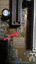
I'm restoring a damaged GA-5AA REV1.1 motherboard and need help identifying missing resistor array RN20 near AGP socket (I marked it on the picture).
Does anyone have this board (maybe a different revision, i think it's not crucial) and could look? Would appreciate!)

Attachments

  • resistor array.jpg
    Filename
    resistor array.jpg
    File size
    82.06 KiB
    Views
    306 views
    File license
    Fair use/fair dealing exception

Reply 3 of 4, by kinetix

User metadata
Rank Member
Rank
Member

Hello my friend. Could you post a photo of the bottom of the rev2.2? if possible in detail the surroundings of the TC40 capacitor.
also, I have downloaded the motherboard manual. More specifically, two manuals, revision 2.2 and 3.2. Being the rev2.2 , this is the one I take as a guide. To test the board, instead of using the K6-2, as a "safety" measure I´m using a Pentium-133. BUT, the jumper/switch configuration in the manual and what is stamped on the board differ slightly!!
Which one do I believe?
also, In the stencil 0 (zero) is ON and X is OFF, as in the manual?

Last edited by kinetix on 2023-09-27, 21:09. Edited 1 time in total.

Reply 4 of 4, by Horun

User metadata
Rank l33t++
Rank
l33t++

I would use the silkscreen print on the board first, if that does not work compare to the manual. Yes, 0 is on X is off (the common nomenclature is 1 for on and 0 for off... stupid people 🤣)
Boards like these suck for too many switches+jumpers to set a simple cpu.... just MHO

Hate posting a reply and then have to edit it because it made no sense 😁 First computer was an IBM 3270 workstation with CGA monitor. Stuff: https://archive.org/details/@horun