VOGONS


First post, by nathanieltolbert

User metadata
Rank Member
Rank
Member

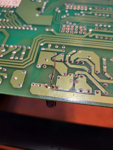
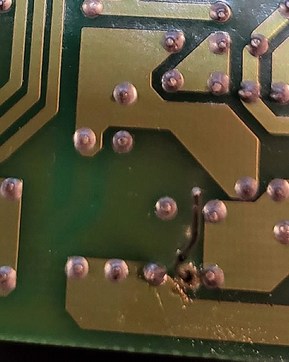
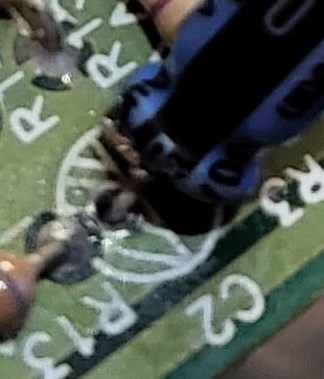
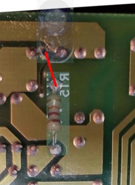
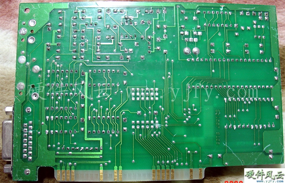
The other day, I was pulling my MPU-IPC-T card that I got from here a decade ago to put in another machine, and I wasn't paying enough attention. The leg on the 10V 100uF cap at the top of the card snapped. I carefully removed the cap, desoldered the leads on the cap with copious amounts of Rosin Soldering Flux, and put the card aside. Today my caps came in so I went to solder them on. It was at that point I realized that I had lifted or destroyed the solder pad on the negative lead for the cap. Of course I didn't notice it until after I tried to solder the new cap on. I am frustrated with myself, I used low heat(I think? 180C is the temp I used), I used my solder sucker, and I added new solder along with the flux, and I still damaged it. It appears to go into a large fill and there are other pins that stick out into the same place, but they appear to be things like resistors. Is there a specific point that I can run a bodge wire from the negative lead on the cap to in order to get the card working again? Apologies if this is in the wrong category. Please take a look at the pictures and make suggestions?

Attachments

  • screwed up 2.jpg
    Filename
    screwed up 2.jpg
    File size
    85.65 KiB
    Views
    743 views
    File license
    Fair use/fair dealing exception
  • Screwed up.jpg
    Filename
    Screwed up.jpg
    File size
    25.79 KiB
    Views
    743 views
    File license
    Fair use/fair dealing exception

Reply 1 of 14, by retardware

User metadata
Rank Oldbie
Rank
Oldbie

What I would do first is to clean up the mess. There is a lot of excess solder that could lead into shorts.
Suck it away, clean up the board with Q-tips and alcohol so that no flux residues remain.
Make sure that traces on the component side are intact, if there are any.
Then replace the cap and add the bodge wire.

Personally I prefer a temperature between 350-400 celsius, so there is enough heat reserve in the solder tip and I get clean shining surfaces and good connections with very short soldering times.
This makes removal of such caps easy too: just heat up both legs simultaneously a moment, then pull them out, and after that suck out the hole so it is open.
The traces tend to come off when one solders too long, no matter the temperature, so it is important to work quickly.

Reply 2 of 14, by nathanieltolbert

User metadata
Rank Member
Rank
Member

After taking the picture I cleaned the board with a small brush and 91% Iso and the flux is pretty much gone except for a small amount round the hole that lost its pad. There is no trace. As you can see in the picture, it just ends in a large green area on the PCB. Is that a ground plane or something? It is the negative leg of the cap. The new cap has already been installed. Where should I run the bodge wire to?

Reply 3 of 14, by keenerb

User metadata
Rank Oldbie
Rank
Oldbie

What does it look like on the front? I pulled up a picture of another MPU-IPC-T and on the back that lead doesn't seem to connec tot anything. I believe whatever it's connected to is on front of pcb, and my guess is that it might be to the ground plane.

http://www.yjfy.com/images/oldhard/sound/MPU-IPC-T_1.jpg

Reply 4 of 14, by nathanieltolbert

User metadata
Rank Member
Rank
Member

Wow, that card you have there looks different from mine entirely. I did the best I could, as I have put away my solder tools, and couldn't remove the cap I put in. I know it's blurry, but I cannot really tell if there is a solder point on the top. Here's a cropped shot of the area.

Attachments

  • screwed up 3.jpg
    Filename
    screwed up 3.jpg
    File size
    25.62 KiB
    Views
    708 views
    File license
    Fair use/fair dealing exception

Reply 5 of 14, by keenerb

User metadata
Rank Oldbie
Rank
Oldbie

Looks like it's connected to the ground plane to me, which makes sense if it's the negative lead.

The back of that card looks different but only the traces, the component placement looks the same to me.

Look at the R1 solder joint at the top-left corner of your picture, how it looks sofr of like a crosshair or X? Does the capacitor hole have that same sort of X?

I really think you could just bridge that capacitor lead to the ground plane pretty much anywhere.

Reply 6 of 14, by canthearu

User metadata
Rank Oldbie
Rank
Oldbie

If the pad still exists on the top side, I will pull the capacitor out and install it bent over, then solder the capacitor on the top side rather than the bottom for that pad that is missing the bottom side.

Set your soldering iron for 400C and get it done quickly to avoid doing more damage. 180C is far too low to do rework with, especially if you have non-leaded solder .... Unless the soldering iron is way out of spec, you wouldn't even melt solder at 180C.

It won't be that pretty, but should be perfectly functional.

Reply 7 of 14, by nathanieltolbert

User metadata
Rank Member
Rank
Member

I have leaded solder. I am using a cheapie KSGER T12 Solder station. 180C does melt my leaded solder, but very slowly. When working with non-leaded solder I usually have it set to 240C. Those are too low? I sadly don't have any classroom experience with solder as my education never called for it. And as much as I enjoy building things with my soldering iron, I don't have a lot of experience, as should be obvious from my terrible solder joints. I can only go off what I find on line and in books in that regards. I have a couple books, but they are very old, and so I cannot really say if they are valid any more. But in regards to the pad as asked by keenerb, the pad in the top left corner of the picture is R13, and it's soldered on both the top and the bottom. Does that make a difference?

Reply 9 of 14, by snufkin

User metadata
Rank Oldbie
Rank
Oldbie

Picture here https://upload.wikimedia.org/wikipedia/common … d_mpu-ipc-t.jpg shows the big copper pour area that looks like it connects to the shield of the rear panel connector, so is probably ground. It looks like the leg of R15 closest to the capacitor connects to this area. If you've got a multimeter then you can check to see if there's a connection between R15 and the back plate. From your photos it looks like the -ve leg of C2 also connects to this area. If that's all true then the neatest way might be to put the capacitor in place as normal, solder the +ve leg, then bend the -ve leg to touch the solder pad of R15 and solder them together. Make sure the legs of the capacitor can't touch each other, you may want to put a bit of plastic sleeving over the -ve leg.

Roland_mpu-ipc-t_bodge.jpg
Filename
Roland_mpu-ipc-t_bodge.jpg
File size
21.3 KiB
Views
644 views
File license
Fair use/fair dealing exception

I think the soldering iron should be hot enough that you only need to hold it in place for a second or two, and you might need to turn it up a bit if trying to solder to a large copper area that can conduct heat away quickly. Those spokes on some of the pads are thermal relief to reduce the amount of heat lost to the copper area, to make soldering easier. Exact temperature will depend on the iron, tip shape, solder type and what you're soldering, but Keenerb's numbers sound like a good starting point. I've also seen 350C for leaded and 400C for lead-free.

Reply 10 of 14, by nathanieltolbert

User metadata
Rank Member
Rank
Member

Okay. I raised my temp on my cheap little KSGER T12 solder pen and checked the board. There was a solder pad for the negative leg on top of the board, so I tried to carefully solder to that pad. The solder held, and made what appears to be a decent connection. I tested the board and it's working now. The solder didn't really seem to melt any faster than where I normally had my temp set. What in the world am I doing wrong? Let me go over my steps and help me identify where I am either missing something or doing something wrong?
Step one, I apply a small amount of flux to the pad. Step two, I then tin the tip of my solder iron. Step three, I apply the tip of the iron to the pth pad. Step four, I wait about a second then I introduce my lead based solder (which is Sn60/Pb40, so 60% Tin and 40% Lead, right?) to the leg of the component and the pad rather than the solder iron tip. Step five, It takes a bit of time for solder to start to melt, meanwhile the flux is sizzling and bubbling. Step six, After the solder melts then I remove the solder wire. Step seven, I wait about a second longer, and remove the solder iron tip and check to see if the joint worked. Most times it does. Step eight, after the joint has solidified and is good, I use a medium strength toothbrush and 91% Isopropyl Alcohol and scrub up the remaining flux.
So this is how it goes when I do soldering. I am going to guess since I have had no formal training and I am only going off what I read and what I see in videos online that I am either missing a step or two, or I am doing something wrong. Recently, a streaming friend sent me a link to videos made by Hakko, and I intend to watch them and see what new methods I can learn. They did warn me that it's more professional than hobbyist videos though, so it may be way over my head.

Reply 11 of 14, by BitWrangler

User metadata
Rank l33t++
Rank
l33t++

I would say there's more of a chance that the pad didn't burn off from heat so much as got eaten off by boiling acid.. flux is not necessary for desoldering IMO. It's purpose is to chemically clean the electrical interfaces so that solder will stick to them. It does bugger all to improve solder flow when desoldering, probably the opposite, in removing heat from the operation. Sure you might need to flux just the tip of the iron from time to time to clean it, but don't overdo it. Then when resoldering a component in, take it easy with the rosin types, the fluxes you see getting hosed everywhere are a weaker acid and isopropyl type. Think to yourself, "Is it okay that I've got a huge blob of boiling acid on this tiny little pad/trace?" and if the answer is no, blot it off a bit if you still are working on it.

Unicorn herding operations are proceeding, but all the totes of hens teeth and barrels of rocking horse poop give them plenty of hiding spots.

Reply 12 of 14, by retardware

User metadata
Rank Oldbie
Rank
Oldbie
nathanieltolbert wrote on 2021-09-28, 14:46:

The solder didn't really seem to melt any faster than where I normally had my temp set. What in the world am I doing wrong? Let me go over my steps and help me identify where I am either missing something or doing something wrong?

nathanieltolbert wrote on 2021-09-28, 14:46:

Step five, It takes a bit of time for solder to start to melt, meanwhile the flux is sizzling and bubbling.

This is what I see when I use a soldering iron that is too weak and needs time to heat up.
This Kgert soldering thing has very thin pens, it looks to me like a 5-10W soldering iron suitable/intended for very fine stuff only, way too small for general purpose electronics works.
A good soldering iron makes the tin melt instantly, so it just flows around the hole and the wire.
I'd prefer even the simplest Weller or Ersa without funky display and all that over that Ksgert thing.

I think one could compare that Ksgert thing with a hammer made of paper.

nathanieltolbert wrote on 2021-09-28, 14:46:

Step one, I apply a small amount of flux to the pad.

This shouldn't be necessary, the electronics solder has a flux core.

nathanieltolbert wrote on 2021-09-28, 14:46:

Step two, I then tin the tip of my solder iron. Step three, I apply the tip of the iron to the pth pad. Step four, I wait about a second then I introduce my lead based solder (which is Sn60/Pb40, so 60% Tin and 40% Lead, right?) to the leg of the component and the pad rather than the solder iron tip.

The solder should flow around and immerse the component's leg as soon as you tip it with the iron.

Reply 13 of 14, by nathanieltolbert

User metadata
Rank Member
Rank
Member
retardware wrote on 2021-09-28, 17:46:
This is what I see when I use a soldering iron that is too weak and needs time to heat up. This Kgert soldering thing has very t […]
Show full quote

This is what I see when I use a soldering iron that is too weak and needs time to heat up.
This Kgert soldering thing has very thin pens, it looks to me like a 5-10W soldering iron suitable/intended for very fine stuff only, way too small for general purpose electronics works.
A good soldering iron makes the tin melt instantly, so it just flows around the hole and the wire.
I'd prefer even the simplest Weller or Ersa without funky display and all that over that Ksgert thing.

I think one could compare that Ksgert thing with a hammer made of paper.

The KSGER I have uses straight standard T12 tips? The reason I bought the KSGER STM32 was because it had a lot of good reviews. The t12 tip I am using is one that I bought from a local store with no brand name that I recognized. Since I have set the temp up to 350 with a boost to 400 C as suggested it's working a lot better than it was. But I had a weller before, a 35W one and it never worked well for me, which is why I started watching and reading reviews on a replacement. I think the KSGER works well enough for the price, and until I can afford a Solder rework station with Hot Air, Desolder gun, and soldering iron from Hakko it works well enough for my needs. I built another HardMPU card after upping my settings and it took my build time from about 35 minutes to a little over 30. And with the higher temp my joints all look shiny, where as they didn't before. So I am thinking a lot of my trouble with soldering, de-soldering in general was because I didn't have my settings set high enough. Oh and the reason why I put flux on the board is because the solder I use does not indicate that it has a rosin or flux core. I have a small spool of solder that does state that it has that, but when I unspool a bit it breaks constantly and seems really brittle. I am guessing I bought a bad batch with that.

-Edit- Fixed formatting error

Reply 14 of 14, by canthearu

User metadata
Rank Oldbie
Rank
Oldbie
nathanieltolbert wrote on 2021-10-01, 15:01:

The KSGER I have uses straight standard T12 tips? The reason I bought the KSGER STM32 was because it had a lot of good reviews. The t12 tip I am using is one that I bought from a local store with no brand name that I recognized. Since I have set the temp up to 350 with a boost to 400 C as suggested it's working a lot better than it was. But I had a weller before, a 35W one and it never worked well for me, which is why I started watching and reading reviews on a replacement. I think the KSGER works well enough for the price, and until I can afford a Solder rework station with Hot Air, Desolder gun, and soldering iron from Hakko it works well enough for my needs. I built another HardMPU card after upping my settings and it took my build time from about 35 minutes to a little over 30. And with the higher temp my joints all look shiny, where as they didn't before. So I am thinking a lot of my trouble with soldering, de-soldering in general was because I didn't have my settings set high enough. Oh and the reason why I put flux on the board is because the solder I use does not indicate that it has a rosin or flux core. I have a small spool of solder that does state that it has that, but when I unspool a bit it breaks constantly and seems really brittle. I am guessing I bought a bad batch with that.

-Edit- Fixed formatting error

The KSGER is a pretty good unit. Most of the work is being done in the T12/T15 tip anyway, as it includes the heater unit internally

If you are using 60/40 lead/tin solder, then you should have shiny joints.