Seems like I'm not eligible to send PMs yet. But I've set up a simple website to allow for easy ordering: https://recnas.org/
Please let me know if this is inappropriate and I'll remove the link asap.
🤷♂️ Dudes selling sound cards, slocket 8 adapters, dream blasters, all sorts of stuff they make here. Seems like it would be unfair to not let you do this. Seems like they don’t like people selling things unless they are making the things…?🤷♂️
The card that connects all of the PCI power lines, how does it not blow itself up in other boards? What is the difference between this mod and a board which supports it natively? Also, what was the card that did this?
I spoke to someone I know who has made some hardware before and he suggested that it would be better to tap the 3.3V from an adjacent AGP slot, if available. He said something about this source of power being "stabilized" as opposed to taking it off of the ATX supply directly. He said that there are about 5 pins or so where it is available from the AGP slot.
What do you guys think about this?
I also contacted someone on eBay who made the -12V ISA power boards but he said that he wasn't interested in trying to make anything similar for the PCI slot.
Kahenrazwrote on 2022-03-09, 03:53:The card that connects all of the PCI power lines, how does it not blow itself up in other boards? What is the difference betwee […] Show full quote
The card that connects all of the PCI power lines, how does it not blow itself up in other boards? What is the difference between this mod and a board which supports it natively? Also, what was the card that did this?
I spoke to someone I know who has made some hardware before and he suggested that it would be better to tap the 3.3V from an adjacent AGP slot, if available. He said something about this source of power being "stabilized" as opposed to taking it off of the ATX supply directly. He said that there are about 5 pins or so where it is available from the AGP slot.
What do you guys think about this?
I also contacted someone on eBay who made the -12V ISA power boards but he said that he wasn't interested in trying to make anything similar for the PCI slot.
It was a 3ware 9550SX SATA Raid card. It is 3.3V only and would normally not go into a 3.3V/5V universal Slot because of the missing notch. But I know ways around that
I didn't look close enough as I've already successfully modified other cards (HP NC370T Gigabit NIC) the same way before, but turns out that not all card makers are building their 3.3V only cards "backwards compatible". It might have worked by masking off all 5V pins though. That's something to try at some point.
Taking the 3.3V from the AGP will also work. Probably depends on the mobo design if there's any benefit from doing so. Proper PCI cards should have their own bypassing caps on the 3.3V and it shouldn't make a big difference.
Can someone with more understanding put together a guide on how to test and make sure the mod will work? I hear that some older mobos use 5v on these pins? Is that true?
Edit:
Catsay on discord wrote:
1It's pretty simple, lookup the PCI slot pinout on wikipedia
2test if you have 5V on all your 3.3V pins of the slot
3If so cut your 5V traces to pins you want to rewire to 3.3V
4But then also make sure your boards chipset is 3.3V PCI signal level tolerant
5Some old PCI boards like SiS496 is PCI potato with 3.3V signals
I think this is an error. There should never be 5V on the 3.3V pins of the slot. The issue that scheiss_freak experienced was a result of drilling through the notch on his card and inserting it into the wrong slot. The problem was on his card, not the motherboard.
I think this is an error. There should never be 5V on the 3.3V pins of the slot. The issue that scheiss_freak experienced was a result of drilling through the notch on his card and inserting it into the wrong slot. The problem was on his card, not the motherboard.
Your entire reply is what I thought, but catsay says that there are early boards that are of concern.
Maybe we can get him to comment further to clarify.
I think this is an error. There should never be 5V on the 3.3V pins of the slot. The issue that scheiss_freak experienced was a result of drilling through the notch on his card and inserting it into the wrong slot. The problem was on his card, not the motherboard.
Can someone with more understanding put together a guide on how to test and make sure the mod will work? I hear that some older mobos use 5v on these pins? Is that true?
Edit:
Catsay on discord wrote:
1It's pretty simple, lookup the PCI slot pinout on wikipedia
2test if you have 5V on all your 3.3V pins of the slot
3If so cut your 5V traces to pins you want to rewire to 3.3V
4But then also make sure your boards chipset is 3.3V PCI signal level tolerant
5Some old PCI boards like SiS496 is PCI potato with 3.3V signals
Catsay == OxCats
The reason I say this is because the PCI standards are a mess when it comes to early boards. Or even budget boards.
There are plenty boards out there, one such example being my Sprint P5N-DP-V3 dual 430NX that have no 3.3V on the PCI slots.
Instead all the pins that on later boards are connected to 3.3V are not left unconnected, but rather they are connected to 5V.
But in general this applies to any AT powered motherboards with PCI, because they have no 3.3V input unless an axillary source is connected!
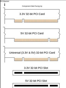
Now this particular board does use this 5V design with the appropriate 5V slot keying of the time of course. So initially all was according to standard.
But this gets fun with more modern mainboards which kept using only the 5V key PCI slots but now introduced mixed 5V and 3.3V on the same connector.
Then 'universal' cards were created that have seemingly 'forgotten' this design and expect 3.3V on various pins while using 5V keying.
Now again look at this diagram and ask yourself when have you ever seen a modern mainboard use a 3.3V PCI slot?
Practically never, in my experience.
That is because they are all a hack, they use mixed voltages 5V and 3.3V on a 5V key slot, which violates the original PCI design spec.
How did I find this out?
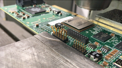
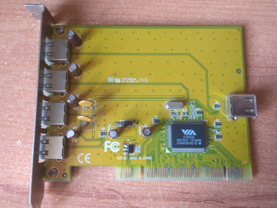
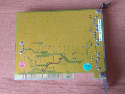
Well one day I was using a PCI USB Card on my AT powered Sprint P5N pentium PCI board and the USB controller got absolutely incredibly hot. (which it did not do in other newer boards).
After much fiddling and multimeter probing around I figured out that all the Voltage pins on the slot were common 5V input and that the card was designed to expect 3.3V on most of them, thus leading to this incredible overheating problem.
I ended up modifying the card by cutting all of the 3.3V (5V connected) traces and converting the card to run 3.3V only from the onboard 5V to 3.3V regulator. Thus making it a true 'universal' card that the original designers failed to make it, because they assumed that some pins would be providing 3.3V.
Thus why I say that If you intend to convert a PCI board to 3.3V capable you absolutely must first probe out the pins to ensure there is no 5V present on the ones you intend to modify.
No assumptions can be made here about standards compliance because board designers fundamentally broke PCI spec for 'ease of use'/'legacy compatibility' purposes.
Especially on AT Powered PCI boards. (which are practically the only ones that adhere to the original design spec)
There are two types of devices, those that know they've been hacked and those that don't yet know they're going to be hacked.
That's pretty terrifying. You're right about the slots as well. I've always wondered if there were ever any 3.3V -only slots in the wild, since I have never seen any.
A diagnostic card, similar to those BIOS code cards, that could be used to identify what voltages a slot is providing and whether there is any problems with it, would be a great tool as well.
What 3.3V regulator did you use there on your modified card?
note there are alignment errors and pads are sized for soldering to back of mobo not for accepting pci slot by its self (if anyone had the idea of using this for a pci footprint)
From here on out I'll modify it to make a 3.3v adapter