VOGONS


First post, by djsubtronic

User metadata
Rank Newbie
Rank
Newbie

Hi guys

So as part of my Compaq LTE 5000 revival project I thought I'd try rebuild the battery as well to make it a fully portable old school machine.

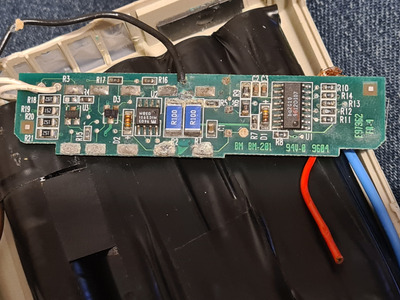
The actual rebuild is not hard - it's simply 10 x 1.2V 17670 NiMH cells in series which can be obtained easily online. The issue lies a bit deeper, and I think has to do with the fact that the little circuit board within the battery is toast due to the corrosion from the original cells.

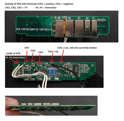
The battery has 5 terminals that connect into the laptop, two of which are the actual positive and negative from the battery. These pass through just fine to the outside of the battery terminal. My first experiment was just using 10 AA batteries, and when I plugged it into the laptop it made that distinct sound that it does whenever any power source was plugged in. So that was a positive sign. However, besides that there were no signs of life when I tried to power it on, no LED no nothing. So I figured the AA batteries probably just don't have enough power to actually turn it on.

I tried something else - I plugged a direct DC 12V power supply into where the cells would normally connect onto the battery circuit board (around 3.42A) so the limitations of AA batteries would be eliminated. This didn't work either, in spite of hearing the distinct "power source connected" sound again. I tried also to omit the battery circuitry entirely and connect a 12V, and even 14V power supply directly to the +/- battery terminals inside the laptop. Same distinct power connected sound again, but no sign of life still. And that was even with 14V/3.42A.

So my next thought is that, there are five terminals - surely they have something to do with it? Maybe the circuitry on that little board in the battery provides a signal to the mobo to allow it to turn on? I don't really know as I've never actually done anything like this before and couldn't find much online about the LTE 5000 battery schematics.

So that's why I'm posting here, if anyone has any knowledge about these old batteries? What are all the pins for? Am I doomed without a working battery circuit board? Etc?

Thanks!

Reply 2 of 9, by wiretap

User metadata
Rank Oldbie
Rank
Oldbie

The extra pins could be several things, but I haven't seen the inside of that battery pack. Could be voltage present, could be cell bank voltage, could be thermistor input, could be other voltage outputs, etc. It would be best to try to clean up the old circuit board inside the battery pack, or duplicate the PCB and rebuild a new one. If you don't know how to do that, obtain another battery pack and hope it isn't damaged. I would really order some proper NiMH batteries to try rebuilding the pack if you still go that route.

My Github
Circuit Board Repair Manuals

Reply 3 of 9, by djsubtronic

User metadata
Rank Newbie
Rank
Newbie
wiretap wrote on 2021-12-21, 02:04:

The extra pins could be several things, but I haven't seen the inside of that battery pack. Could be voltage present, could be cell bank voltage, could be thermistor input, could be other voltage outputs, etc. It would be best to try to clean up the old circuit board inside the battery pack, or duplicate the PCB and rebuild a new one. If you don't know how to do that, obtain another battery pack and hope it isn't damaged. I would really order some proper NiMH batteries to try rebuilding the pack if you still go that route.

Thanks - I have no idea about rebuilding PCB so that's not an option for me. If I post a pic of the PCB and the terminals would that help at all? Can't find any details about it online (or a battery pack for that matter).

Reply 6 of 9, by snufkin

User metadata
Rank Oldbie
Rank
Oldbie

Any chance of a high-res/less blurred/brighter lit copy of the front and back with the wires held out of the way? Ideally want to be able to see all the traces and part numbers. Looks like there's both the thermistor that I assume goes out to the middle of the pack, and I think there's also a PTC type fuse stuffed under CN4&5, opposite those two 0.1ohm (I think) power resistors, which must be a sort of current limiter. That MIC2951-03BM is a 5V regulator, but it's difficult to see what it supplies. I can't make out the part number for U1 (bq2610?), I assume it's a battery status monitor of some sort. Corrosion around R5 looks pretty bad, might be worth checking the resistance across it. Maybe there's some sort of battery status/check handshake thing that goes on between laptop and battery (that U1 chip?) which if it fails the laptop won't use the battery. Or the laptop needs 5V from U2 on CN3 (assuming U2 connects to that)?

Reply 8 of 9, by snufkin

User metadata
Rank Oldbie
Rank
Oldbie

Thanks. It looks like there's some corrosion damage, and that's making it hard to see where various tracks go, particularly how P1 and P2 get to any of the CN contacts. I suspect there may be a track somewhere that's been cut by corrosion.

The bq2010 (U1) is a battery status monitoring chip, which supports a one wire communication protocol. So it's possible that one of the 5 pins goes there, maybe CN2. Maybe the laptop will refuse to use the battery unless it can read a charge level from U1. CN1 looks to be the thermistor output, possibly outputs a voltage based on the temperature. Have you got a multimeter? One interesting thing to check is where pin 1 of the MIC2951 goes to. pin 8 should go to battery +ve and pin 4 to battery -ve. Pin 1 is a 5V output which I'm assuming is eventually connected to the thermistor and U1, but I can't see how.

I think to figure this out then you might need to fully work out what the circuit does, which will mean removing quite a few components to look where tracks go under the components. Particularly the 5 battery contacts and the PTC, and U1, U2 R1 and R2 on the component side. Given the corrosion that may be a good idea anyway so you can clean under the components to stop any further damage. It's a shame there seems to be no documentation about what the pins are. Hopefully someone else might have a working battery and be able to measure the voltages on each pin.

Reply 9 of 9, by djsubtronic

User metadata
Rank Newbie
Rank
Newbie
snufkin wrote on 2021-12-23, 00:42:

Thanks. It looks like there's some corrosion damage, and that's making it hard to see where various tracks go, particularly how P1 and P2 get to any of the CN contacts. I suspect there may be a track somewhere that's been cut by corrosion.

The bq2010 (U1) is a battery status monitoring chip, which supports a one wire communication protocol. So it's possible that one of the 5 pins goes there, maybe CN2. Maybe the laptop will refuse to use the battery unless it can read a charge level from U1. CN1 looks to be the thermistor output, possibly outputs a voltage based on the temperature. Have you got a multimeter? One interesting thing to check is where pin 1 of the MIC2951 goes to. pin 8 should go to battery +ve and pin 4 to battery -ve. Pin 1 is a 5V output which I'm assuming is eventually connected to the thermistor and U1, but I can't see how.

I think to figure this out then you might need to fully work out what the circuit does, which will mean removing quite a few components to look where tracks go under the components. Particularly the 5 battery contacts and the PTC, and U1, U2 R1 and R2 on the component side. Given the corrosion that may be a good idea anyway so you can clean under the components to stop any further damage. It's a shame there seems to be no documentation about what the pins are. Hopefully someone else might have a working battery and be able to measure the voltages on each pin.

Thank you for the detailed response.

I'm not sure how P1 and P2 goes to the respective CN4 and CN5 terminals, but they do because I've tested that with a multimeter while I had my makeshift battery pack wired up to it. So that part is not an issue, but what you say about the rest of the control circuitry makes sense. However I don't really have the skills/knowledge or tools to start manipulating it i.e. removing or re-soldering components etc.

I do have a second board from a different battery pack, also with some corrosion but on closer inspection I now realise that this other board is actually different - in fact might be slight simpler too. I'm going to give it a good clean and then post another pic, maybe something more can be derived from that.