VOGONS


First post, by alpm

User metadata
Rank Newbie
Rank
Newbie

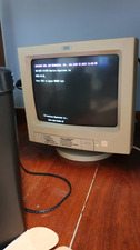
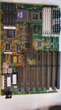
Hi, I have just acquired this 386 board on ebay (seems to be from TI, but there is also an HT/HD symbol, maybe Headland?). The model seems to be HT BV-0 E105181. On the boot screen it reads in the bottom BT13-1187-011091-KF.

Once turned on, it is intermittently failing with "CMOS inoperational System Halted" or three long beeps. Most of the times the error happens during memory test. When I manage to get into the CMOS setup, the clock/time starts and behaves normally but then, after 10s or so, the seconds part of the time starts to jump erratically (e.g. 0 -> 10 -> 5 -> 32) and then stops. Then, on the next boot, it will either boot and fail during memory test (CMOS inoperational system halted), or not boot and error with 3 long beeps (indicating a memory failure).
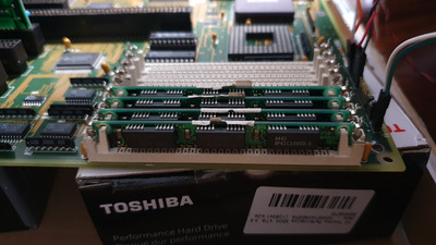
If I remove the memories (clean them with a rubber) and place them again, sometimes this will make the machine boot past the memory check, but the CMOS will still show the erratic time behavior (in some occasions it will fail from within CMOS setup). Other memories (80ns) I tested show the same behavior.

Some notes about the motherboard:

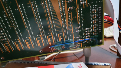
  • It has two broken tantaluns near the power supply connector
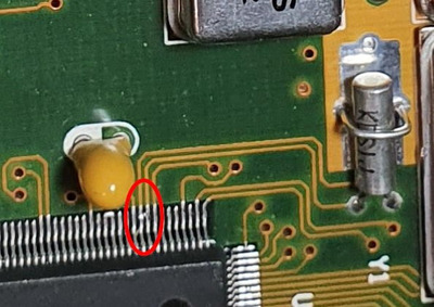
  • There is a cracked tantalum near the second memory module
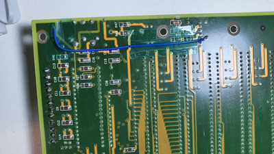
  • The trace connecting to the "+" of the battery connector is broken, so I bodged it with a wire
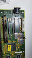
  • It seems someone tried to repair the power connector, given the fresh solder points there

Can you folks help? Could this be due to bad tantaluns? Or maybe something in the oscillators?

Attachments

Last edited by alpm on 2021-12-31, 17:55. Edited 1 time in total.

Reply 1 of 32, by Deksor

User metadata
Rank l33t
Rank
l33t

"CMOS inoperational system halted" sounds like an error with the RTC to me. Maybe it's simply because the battery is missing ? Try to add a battery to the circuit ?

Interesting board, manufacturer code 1187 is undocumented, if we can find who that is, it'd be pretty cool ! I have never seen that Austek chip on a board before ! Neither that errror.

Could you please dump the bios if you can right now, or dump it when the PC will be working ? That way we can add it to ultimateretro

Trying to identify old hardware ? Visit The retro web - Project's thread The Retro Web project - a stason.org/TH99 alternative

Reply 2 of 32, by pentiumspeed

User metadata
Rank l33t
Rank
l33t

Austek existed for very short time frame. Asutek developed a cache controller alternative to Intel's.

Cheers,

Great Northern aka Canada.

Reply 4 of 32, by alpm

User metadata
Rank Newbie
Rank
Newbie

I will certainly publish the bios rom! I tried to boot now, but I didn't manage to do so. The system keeps failing with the 3 long beeps. After 4h-8h it usually boots up (when there is no battery present).
I've downloaded AFU DOS 4.4 from AMI. Would this be the right tool to dump the BIOS? I don't have a MiniPRO or similar to dump, but if I fail to boot the system I will acquire one and post the dump here.

I added a single brand new Sony CR-2032 to the battery circuit. I tried adding a 1.5V battery (in series) to bump the voltage to 4.5V, but that didn't change the outcome.
The board will often boot when the battery is present.

Reply 5 of 32, by alpm

User metadata
Rank Newbie
Rank
Newbie

I wonder what "CN1" is for. An additional RAM-card?

I think so! It would be lovely to find the manual for this board. I will ask the seller if they have more information on it.
BTW, this was the ad https://www.ebay.com/itm/265391155051.

Reply 6 of 32, by snufkin

User metadata
Rank Oldbie
Rank
Oldbie

Found a possible match on ultimate retro: https://www.ultimateretro.net/en/motherboards/2091
Layout looks the same.

Anyway, yes the missing/failed tants will mean the power supply voltages will be noisy, which can cause many weird problems. Also, what are you using for the external battery? If the chip under the yellow sticker is a TACT83443: http://www.dosdays.co.uk/media/texas_instrume … 0/datasheet.pdf then pin 63 should be at the battery voltage. Looks like there might be a convenient via next to the pin to measure that voltage.

[edit: actually, not quite a match as the external battery header is in a different place]
[edit: if it is that TI chipset then Vbatt should be between 3-5.5V, so the 4.5V you've tried should be ok, even with a diode drop between battery and chipset]

Last edited by snufkin on 2021-12-31, 18:09. Edited 2 times in total.

Reply 7 of 32, by BitWrangler

User metadata
Rank l33t++
Rank
l33t++

First step, try a battery on it.

However there's a couple of things I'm not happy with, from the getting an unknown board to exhibit full functionality point of view... i) The 66 Mhz crystal implies that the board is hardwired for 33Mhz, and I don't see enough jumpers in the right areas to be convinced that's settable. Therefore a 25Mhz CPU may be overclocked, which can lead to spurious operation unless carefully tweaked and tuned, or maybe is one of the "losing tickets" i.e. a CPU that won't overclock. ii) The cache at 25ns is a bit on the slow side for 33Mhz operation also, I would prefer to see 20ns in it.. Seems like this board might have been bare at one point and someone just stuck available parts in it, whether they were ideal or not.

Unicorn herding operations are proceeding, but all the totes of hens teeth and barrels of rocking horse poop give them plenty of hiding spots.

Reply 8 of 32, by computerguy08

User metadata
Rank Member
Rank
Member
snufkin wrote on 2021-12-31, 17:55:

Found a possible match on ultimate retro: https://www.ultimateretro.net/en/motherboards/2091
Layout looks the same.

Yes, this is a 100% match, both on the jumper labels and the location of the components on the board. This is the board OP has.

Reply 9 of 32, by alpm

User metadata
Rank Newbie
Rank
Newbie

You folks are AWESOME! Thank you so much for all the replies so far.

snufkin wrote on 2021-12-31, 17:55:
Found a possible match on ultimate retro: https://www.ultimateretro.net/en/motherboards/2091 Layout looks the same. […]
Show full quote

Found a possible match on ultimate retro: https://www.ultimateretro.net/en/motherboards/2091
Layout looks the same.

Anyway, yes the missing/failed tants will mean the power supply voltages will be noisy, which can cause many weird problems. Also, what are you using for the external battery? If the chip under the yellow sticker is a TACT83443: http://www.dosdays.co.uk/media/texas_instrume … 0/datasheet.pdf then pin 63 should be at the battery voltage. Looks like there might be a convenient via next to the pin to measure that voltage.

[edit: actually, not quite a match as the external battery header is in a different place]

Wow, that indeed looks like the board I have! Fantastic!
Also, you are right on the spot about the chip under the "003.". It is a TACT83443GPP. I've measured pin 63 (there was a via hole, probed there) against the battery ground (is this the right way?) and it read 1.642V (system turned off). Should I measure it with it on?
This seems wrong, right?

​For battery I'm using a CR2032 on the 4 pin battery header (I've placed the battery + on pin 1).

Reply 10 of 32, by alpm

User metadata
Rank Newbie
Rank
Newbie

Hi BitWrangler, thanks for the analysis!

BitWrangler wrote on 2021-12-31, 17:56:

First step, try a battery on it.

I'm using a CR2032, do you think this should work?

BitWrangler wrote on 2021-12-31, 17:56:

However there's a couple of things I'm not happy with, from the getting an unknown board to exhibit full functionality point of view... i) The 66 Mhz crystal implies that the board is hardwired for 33Mhz, and I don't see enough jumpers in the right areas to be convinced that's settable. Therefore a 25Mhz CPU may be overclocked, which can lead to spurious operation unless carefully tweaked and tuned, or maybe is one of the "losing tickets" i.e. a CPU that won't overclock. ii) The cache at 25ns is a bit on the slow side for 33Mhz operation also, I would prefer to see 20ns in it.. Seems like this board might have been bare at one point and someone just stuck available parts in it, whether they were ideal or not.

That's concerning. What would be the ideal approach in your opinion? Should I try to find a 33MHz 386 and replace it? As for the cache, should I try to swap the memory chips?

Sorry for the many questions folks, I'm a complete noob on these 286/386 era boards.

Reply 11 of 32, by alpm

User metadata
Rank Newbie
Rank
Newbie

Just tried adding a 1.5v "boost" (LR-44 battery in series). Pin 63 measured 3.0V against the battery ground pin (system off).
When the system is on, pin 63 against pin 204 (GND) reads 4.8V.

Last edited by alpm on 2021-12-31, 18:45. Edited 1 time in total.

Reply 12 of 32, by majestyk

User metadata
Rank Oldbie
Rank
Oldbie

3V will do.

The 25 MHz CPU is overclocked by 32% at the moment. This c a n be o.k, but it could also incur instabilities.

Did you test with the Turbo-Switch closed? (This should take care of the overclocking)

Reply 13 of 32, by alpm

User metadata
Rank Newbie
Rank
Newbie
majestyk wrote on 2021-12-31, 18:47:

3V will do.

The 25 MHz CPU is overclocked by 32% at the moment. This c a n be o.k, but it could also incur instabilities.

Did you test with the Turbo-Switch closed? (This should take care of the overclocking)

Yes, the turbo switch is closed (and turbo LED is on). Would this be the right approach?

Reply 14 of 32, by majestyk

User metadata
Rank Oldbie
Rank
Oldbie

If there´s no difference between Turbo and Non-Turbo mode, then the 25MHz CPU running at 33 MHz is not the problem. At least not at themoment until you have fixed the CMOS error message.

Since there has been considerable battery leakage in the past you should remove both BIOS and Keyboard-Controller and check the traces / vias underneath carefully.

Reply 15 of 32, by alpm

User metadata
Rank Newbie
Rank
Newbie
majestyk wrote on 2021-12-31, 18:53:

If there´s no difference between Turbo and Non-Turbo mode, then the 25MHz CPU running at 33 MHz is not the problem. At least not at themoment until you have fixed the CMOS error message.

Makes sense. Thank you for the tip!

majestyk wrote on 2021-12-31, 18:53:

Since there has been considerable battery leakage in the past you should remove both BIOS and Keyboard-Controller and check the traces / vias underneath carefully.

Alright! Thank you! I will do this and once checked, I will post an update here.

Reply 16 of 32, by alpm

User metadata
Rank Newbie
Rank
Newbie

I've removed the chips. The traces seem alright!
I tried to boot after re-seating and cleaning the sockets, but the "3 long beeps" remained.

Should I be trying something different?

Attachments

Reply 17 of 32, by snufkin

User metadata
Rank Oldbie
Rank
Oldbie

I'm still suspicious of the missing/cracked tants that you've found. But also might be worth checking the pins on the that 443 closely to check for any soldering issues. From the photo it looks like there's something odd on pins 61&62 which are the crystal connections.

Attachments

  • 443_Pin61_62.jpg
    Filename
    443_Pin61_62.jpg
    File size
    52.12 KiB
    Views
    946 views
    File license
    Fair use/fair dealing exception

Reply 19 of 32, by computerguy08

User metadata
Rank Member
Rank
Member
snufkin wrote on 2021-12-31, 21:48:

I'm still suspicious of the missing/cracked tants that you've found. But also might be worth checking the pins on the that 443 closely to check for any soldering issues. From the photo it looks like there's something odd on pins 61&62 which are the crystal connections.

Those "bridged" pins go right to the 32kHz crystal oscillator, which should be responsible for the RTC timer (normally a 6818A, this one is bundled in the big Ti chip). I bet that's going to be an issue, so fixing it might get the board to boot.