VOGONS


First post, by ciornyi

User metadata
Rank Member
Rank
Member

Hello retro fellas !

Just bought this board and find out it have audio onboard vibra16 vx chip. So i would be much appreciated to get manual or pinout for built in sound blaster.

Attachments

  • abv.jpg
    Filename
    abv.jpg
    File size
    967.25 KiB
    Views
    817 views
    File comment
    full size
    File license
    Public domain
  • 88233.jpg
    Filename
    88233.jpg
    File size
    468.44 KiB
    Views
    883 views
    File comment
    8823
    File license
    Public domain
Last edited by ciornyi on 2022-01-16, 07:06. Edited 1 time in total.

DOS: 166mmx/16mb/Y719/S3virge
DOS/95: PII333/128mb/AWE64/TNT2M64
Win98: P3_900/256mb/SB live/3dfx V3
Win Me: Athlon 1700+/512mb/Audigy2/Geforce 3Ti200
Win XP: E8600/4096mb/SB X-fi/HD6850

Reply 1 of 15, by weedeewee

User metadata
Rank l33t
Rank
l33t

Are you sure that is a pcchips mainboard?
Can you post a photo of the whole board ?

Right to repair is fundamental. You own it, you're allowed to fix it.
How To Ask Questions The Smart Way
Do not ask Why !
https://www.vogonswiki.com/index.php/Serial_port

Reply 2 of 15, by snufkin

User metadata
Rank Oldbie
Rank
Oldbie

Think it's one of these: https://www.ultimateretro.net/en/motherboards/6634#downloads

Manual says the header CN31 is the sound cable connector, but doesn't give a pin out. JP 20,21,22 all need to be set to 1-2 to enable the sound.

That header contains a line out, mic-in, line in and CD-in, plus game port. Will be a bit of work, but not too bad, to trace which is which.

[edit: sorry, not a CD in. From the manual: "Speaker out (Line-out), Mic-in, one Line-in and MIDI/Game port (via a cable)." ]

[edit: think I found a header listing in 'Electronics For You Jan 2001: 'Build your own PIII'', where they used a PCPartner board, but don't say which. Fair chance they kept the same pinout from one board to the next]

PCPartner_AudioHeader.jpg
Filename
PCPartner_AudioHeader.jpg
File size
53.37 KiB
Views
842 views
File license
Fair use/fair dealing exception

[last edit, honest... Photos of the front and back of the whole board would be good for the Ultimate Retro for that board]

Reply 3 of 15, by ciornyi

User metadata
Rank Member
Rank
Member

Thank you for reply .
I've updated full size board , and made measures for ground pins. Its mismatch pinout you privided me.

Attachments

  • 88233.jpg
    Filename
    88233.jpg
    File size
    75.72 KiB
    Views
    814 views
    File comment
    gnd pinout
    File license
    Public domain

DOS: 166mmx/16mb/Y719/S3virge
DOS/95: PII333/128mb/AWE64/TNT2M64
Win98: P3_900/256mb/SB live/3dfx V3
Win Me: Athlon 1700+/512mb/Audigy2/Geforce 3Ti200
Win XP: E8600/4096mb/SB X-fi/HD6850

Reply 4 of 15, by Roman555

User metadata
Rank Oldbie
Rank
Oldbie
ciornyi wrote on 2022-01-16, 07:43:

Thank you for reply .
I've updated full size board , and made measures for ground pins. Its mismatch pinout you privided me.

It depends how to count pins ) Where do you think the pin #2 is ?

[ MS6168/PII-350/YMF754/98SE ]
[ 775i65G/E5500/9800Pro/Vortex2/ME ]

Reply 5 of 15, by ciornyi

User metadata
Rank Member
Rank
Member
Roman555 wrote on 2022-01-16, 07:49:
ciornyi wrote on 2022-01-16, 07:43:

Thank you for reply .
I've updated full size board , and made measures for ground pins. Its mismatch pinout you privided me.

It depends how to count pins ) Where do you think the pin #2 is ?

Really ?Its counting always same way 🤣

DOS: 166mmx/16mb/Y719/S3virge
DOS/95: PII333/128mb/AWE64/TNT2M64
Win98: P3_900/256mb/SB live/3dfx V3
Win Me: Athlon 1700+/512mb/Audigy2/Geforce 3Ti200
Win XP: E8600/4096mb/SB X-fi/HD6850

Reply 6 of 15, by Roman555

User metadata
Rank Oldbie
Rank
Oldbie
ciornyi wrote on 2022-01-16, 07:52:
Roman555 wrote on 2022-01-16, 07:49:
ciornyi wrote on 2022-01-16, 07:43:

Thank you for reply .
I've updated full size board , and made measures for ground pins. Its mismatch pinout you privided me.

It depends how to count pins ) Where do you think the pin #2 is ?

Really ?Its counting always same way 🤣

Yes, I think so. But you didn't answer. My example:
07fig03_alt.jpg

[ MS6168/PII-350/YMF754/98SE ]
[ 775i65G/E5500/9800Pro/Vortex2/ME ]

Reply 7 of 15, by ciornyi

User metadata
Rank Member
Rank
Member
Roman555 wrote on 2022-01-16, 08:03:
Yes, I think so. But you didn't answer. My example: https://ptgmedia.pearsoncmg.com/images/chap7_9780789750006/elementLinks/07f […]
Show full quote
ciornyi wrote on 2022-01-16, 07:52:
Roman555 wrote on 2022-01-16, 07:49:

It depends how to count pins ) Where do you think the pin #2 is ?

Really ?Its counting always same way 🤣

Yes, I think so. But you didn't answer. My example:
07fig03_alt.jpg

Ok pin2 is at bottom

DOS: 166mmx/16mb/Y719/S3virge
DOS/95: PII333/128mb/AWE64/TNT2M64
Win98: P3_900/256mb/SB live/3dfx V3
Win Me: Athlon 1700+/512mb/Audigy2/Geforce 3Ti200
Win XP: E8600/4096mb/SB X-fi/HD6850

Reply 9 of 15, by snufkin

User metadata
Rank Oldbie
Rank
Oldbie
ciornyi wrote on 2022-01-16, 07:52:

Really ?Its counting always same way 🤣

Unfortunately there are at least three different ways to count pins:

1) 8 7 6 5   [e.g. DIP chips]
1 2 3 4

2) 5 6 7 8 [e.g. SDRAM card edge]
1 2 3 4

3) 2 4 6 8 [e.g. IDE headers, things with IDC flat cables]
1 3 5 7

In this case I'd assume it's arranged like the last one because it'd very likely be going to a flat cable with an IDC connector. So the wires in the cable will be 1-26, with the red stripe for wire 1. The way the IDC connectors work that means wire 2 will connect to the pin opposite pin 1, then wire 3 connects to the pin next to pin 1, and so on. Plus it means that the potentially noisy digital signals on the gameport/MIDI pins are put at one end of the connector, with the analogue audio signals at the other end. Thanks for you measurements and to Roman555 for checking off that the Grounds you found match up with the pinout if you pick the right counting method.

Either PCPartner, or the writers of the article where I found the pinout, don't seem to have been able to pick a counting method. Looking at the pinouts given for whichever PCPartner board they used, it looks like they use method 1 for the USB header numbering, method 2 for the LPT header and method 3 for the sound and IDE headers. Exciting.

Reply 10 of 15, by Roman555

User metadata
Rank Oldbie
Rank
Oldbie
snufkin wrote on 2022-01-16, 11:57:

Unfortunately there are at least three different ways to count pins:

Thank you for the clarification and addition.

[ MS6168/PII-350/YMF754/98SE ]
[ 775i65G/E5500/9800Pro/Vortex2/ME ]

Reply 11 of 15, by ciornyi

User metadata
Rank Member
Rank
Member

Thank you for reply . You are talking reasonable but there is still doubds as i found this pinout from PCCHIPS M598

Attachments

  • M598.jpg
    Filename
    M598.jpg
    File size
    117.47 KiB
    Views
    716 views
    File comment
    M598
    File license
    Public domain

DOS: 166mmx/16mb/Y719/S3virge
DOS/95: PII333/128mb/AWE64/TNT2M64
Win98: P3_900/256mb/SB live/3dfx V3
Win Me: Athlon 1700+/512mb/Audigy2/Geforce 3Ti200
Win XP: E8600/4096mb/SB X-fi/HD6850

Reply 12 of 15, by weedeewee

User metadata
Rank l33t
Rank
l33t

they do seem to line up pretty much
only difference seems to be swapped line-in,out and joystick pot number & joystuck button number

VCC		VCC
VCC VCC
SWC SWC
SWA SWA
XTC TIMB *
XTA TIMC *
MSOUT TXD
GND GND
XTD TIMA *
GND GND
SWB SWD *
XTB TIMC *
MSIN RXD
SWD SWB *
NC NC
VCC VCC
Lineout line-in *
Lineout line-in *
GND gnd line
GND gnd mic
Mic-in micp
Mic-in mic in
NC gnd
GND gnd line out
line-in line out *
line-in line out *

easiest test would be to verify if pin 25,26 is a line out by hooking it up to an amplifier.

Right to repair is fundamental. You own it, you're allowed to fix it.
How To Ask Questions The Smart Way
Do not ask Why !
https://www.vogonswiki.com/index.php/Serial_port

Reply 13 of 15, by snufkin

User metadata
Rank Oldbie
Rank
Oldbie

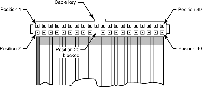
Thanks for the table, it's got some useful extra information. Thanks to Weedeewee for aligning the pinouts using what I think is the sensible numbering method. It looks like PCChips were numbering the pins using Option 2 from my examples, when PCPartner used Option 3. But that's just numbering/labeling things, what really matters is where the pin actually physically is.

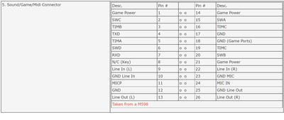
It's a bit of a mixed bag between the two pinouts on the joystick switches. Based on the 15pin dsub Gameport pinout, I think the PCPartner pinout probably has SWD and SWB the wrong way around, but the PCChips has the analogue pins wrong, at the very least by duplicating TIMC and missing off TIMD.

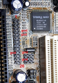
It's also interesting that the PCChips makes it clear which Ground is for which input/output, and also which of the Mic lines is the signal input and which the 5V sort-of phantom power. But neither tell you which is L or R for the line in/out. Actually, on the grounds, note that PCChips says 23 should be Ground and PCPartner says it should be NC, and you didn't measure it as Ground. So that suggests the PCPartner pinout is the closer match for at least that pin.

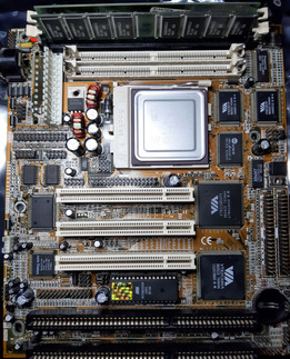
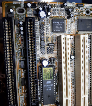
This all seems to match with the SMD components next to the header. There's a 2.2k resistor, which is probably a current limiter going to MicP/pin 21, with 3 capacitors above (probably DC blocking for the Mic and one of the Lines) and 2 capacitors below (probably DC blocking for the other Line). Might be interesting to see if you can measure a voltage on pin 21 or pin 22.

Other than that, as Weedeewee says, easiest way to test at this point is to wire up a 3.5mm socket with pin 24-sleeve, 25-tip, 26-ring. I'm guessing that pin 25/26 is L/R. Plug a cable from the socket to an amp, then if you play something (assuming whatever OS you're using sees the device) then if you get sound out it's line out. If you don't then try playing something in to it (quietly) and see if you can record something and see a signal, in which case it's line in.

Reply 14 of 15, by weedeewee

User metadata
Rank l33t
Rank
l33t
snufkin wrote on 2022-01-17, 20:27:

But neither tell you which is L or R for the line in/out.

Actually, it is indicated on the pcchips layout, I just ommited it.
Also, all the ground are probably connected to each other. The different labeling is just that, labeling.

Right to repair is fundamental. You own it, you're allowed to fix it.
How To Ask Questions The Smart Way
Do not ask Why !
https://www.vogonswiki.com/index.php/Serial_port

Reply 15 of 15, by snufkin

User metadata
Rank Oldbie
Rank
Oldbie
weedeewee wrote on 2022-01-18, 06:20:
snufkin wrote on 2022-01-17, 20:27:

But neither tell you which is L or R for the line in/out.

Actually, it is indicated on the pcchips layout, I just ommited it.
Also, all the ground are probably connected to each other. The different labeling is just that, labeling.

Ah, so it is. At least I guessed L/R correctly. Does that make up for not reading properly?

Yeah, the grounds will ultimately connect together. But potentially they could be kept separate on the motherboard until they reach the sound chip and only join together there. Could even split them so that, for example, the Line-Out ground runs either side of the Line Out L/R, as a sort of shield. Join all the analogue grounds at the sound chip, then connect to the system ground at just one point, possibly through an inductor/ferrite. Isolate the ground plane under the traces from the system ground and connect that to the analogue ground as well. So the pairs are then reasonably isolated from each other, and well isolated from the digital noise on the system ground. If all that's done, then it'll improve signal quality (very slightly) if the correct ground is used with the correct pair. Maybe L16 or L6 are for isolating either the analogue Vcc or Ground.

Looking at the photo of the area, I don't think there's any fancy routeing here though (I think maybe the audio traces run alongside traces going to the BIOS), so it probably doesn't matter, as long as the Ground pins for the gameport aren't used. I think. Good analogue and ground design is something of a mystery.